
Operation and maintenance manual


Section 200-0051
SM 1399 5-98
1
FUEL SYSTEM - Electronic Foot Pedal
SM - 1478
DESCRIPTION
Numbers in parentheses refer to Fig. 1.
The electronic foot pedal assembly provides an
electrical signal to the engine's fuel control system in
proportion to the degree of pedal actuation. Maximum
and minimum stops are built into the pedal assembly
during manufacture. The pedal assembly comes
preset and therefore no adjustment is necessary.
Note: The DDEC controlled engine will override the
pedal position until the engine is warmed up to the
correct operating temperature. The engine MUST be
started with foot 'OFF' pedal assembly (1).
Kickdown switch (17), which can be used when
automatic range is selected, allows for the possibility
of selecting a lower gear by pressing down fully on
pedal assembly (1) and holding. This can be used to
provide a downshift on demand provided that the
vehicle speed is within the range allowable. That is,
the vehicle is not travelling at a speed that would result
in the engine overspeeding in the lower gear. To
disengage the transmission kickdown, allow pedal
assembly (1) to return to the full load or part load
position. Refer to Section 120-0010, TRANSMISSION
AND MOUNTING
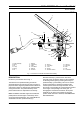
Fig. 1 - Electronic Foot Pedal and Kickdown Assembly
1 - Pedal Assembly
2- Spring
3- Pin
4 - 'E' Clip
5- Spring
6- Pin
7 - Bearing
8 - Pedal Stop
9- Plate
10 - Pivot Block
11 - Bellows
12 - Rod End
13 - Spring
14 - Lever Stop
15 - Lever
16 - Sensor
17 - Kickdown Switch
18 - Harness
19 - Grommet
20 - Bolt
21 - Nut
22 - Lockwasher
18
1
2
3
4
5
6
7
8
9
10
11
12
13
14
15
16
17
19
20
21,22