
Operation and maintenance manual


Section 165-0015
Brake Assembly - Oil Cooled Disc Brakes
4
SM 2167 Rev 1 10-03
5. Remove the wear indicator cap (7) only at this
stage. Remove the plugs and fittings for the cooling
lines and the actuation lines from the brake inner cover
(15). Note locations of plugs and fittings to aid in
Assembly.
SM - 3093
Fig. 6 - Removing Fittings
6. Remove the capscrews (22) and washers (23) from
brake outer cover (24).
SM - 3094
Fig. 7 - Removing Capscrews
7. Remove the brake cover (24), the retractor springs
(28) and 'O' ring (25). Remove the friction discs (26),
reaction discs (27) and piston pressure plate (30) from
the housing (31) as shown in Fig. 8.
Remove the spring guide pins (29) from the piston
pressure plate (30).
SM - 3095
Fig. 8 - Removing Discs
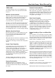
SM - 3096
Fig. 9 - Puller Hole Locations
8. Remove brake piston (21) from housing (31). It may
be necessary to use puller holes as shown in Fig. 9.