
Operation and maintenance manual


Section 165-0015
Brake Assembly - Oil Cooled Disc Brakes
2
SM 2167 Rev 1 10-03
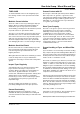
Fig. 1 - Brake Pack Explosion
1 - Brake Assy (6 Plate)
2 - Slack Adjuster Nut
3 - Slack Adjuster Seal
4 - Slack Adjuster Jam Nut
5 - Slack Adjuster Seal
6 - Slack Adjuster Screw
7 - Wear Indicator Cap
8 - 'O' Ring
9 - Wear Indicator Pin
10 - Drain Plug
Section 160-0030, AXLE GROUP (HUB) and Section
160-0020, DIFFERENTIAL DRIVE HEAD.
5. Refer to Section 160-0030, AXLE GROUP (HUB) for
disassembly instructions.
6. Attach suitable lifting equipment to brake assembly
(40) and support weight. Loosen and remove capscrews
(35) and ring (34) securing brake assembly (40) to axle
stub (29).
7. With brake assembly (40) supported, remove brake
assembly (40) from axle stub (29).
8. Place brake assembly (40) on a clean work surface
for disassembly.
9. Remove and discard 'O' ring (39) and oil seals (37)
from brake assembly.
11 - 'O' Ring
12 - Plug
13 - 'O' Ring
14 - Bleeder Screw
15 - Brake Inner Cover
16 - Dowel Pin
17 - 'O' Ring
18 - 'O' Ring
19 - Piston Inner Seal
20 - Piston Outer Seal
21 - Brake Piston
22 - Capscrew
23 - Washer
24 - Brake Outer Cover
25 - 'O' Ring
26 - Friction Disc
27 - Reaction Disc
28 - Retractor Spring
29 - Guide Pin
30 - Piston Pressure Plate
31 - Brake Housing
SM - 2775