
Operation and maintenance manual


Section 160-0030
SM 2147 Rev 1 10-03
5
into planet carrier (19) and through first washer (4),
planet gear (5) and second washer (6) making sure to
line up flat on planet pin (22) with hole in planet carrier
(19) for grub screw (18).
8. Clean grub screw (18) threads with suitable solvent
then apply Loctite 275. Fit grub screw (18) into hole in
planet carrier (19) and tighten to a torque of 30 - 36 Nm
(22 - 27 lbf ft) to secure planet pin (22) assembly.
9. Repeat steps 2 through 8 for the other two planet
gear (5) assemblies.
10. Peen over grub screw (18) in four places to lock in
position.
11. Coat thrust button (7) bore in planet carrier (19)
with Loctite 275 then fit thrust button (7).
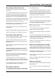
Installation of Axle Stub
1. Clean mating faces of axle stub (29) and axle
Rear Axle Group - Axle Group (Hub)
housing (41).
2. Apply a coating of Loctite 515 to mating faces using
a roller.
3. Using suitable lifting equipment, offer axle stub (29)
up to axle housing (41), ensuring small counterbored
hole for retaining capscrew (30) is in line with its tapped
hole in axle housing (41).
4. Tap axle stub (29) into position using a hide faced
mallet and insert retaining capscrew (30) into axle stub
(29)/axle housing (41). Tighten capscrew (30) to 372 -
412 lbf ft (505 - 559 Nm).
Note: The use of two short bolts (similar to item 35)
may help in drawing on the axle stub.
Installation of Brake Assembly
1. Clean 'O' ring groove in brake assembly (40) and
insert a new 'O' ring (39). Smear new 'O' ring with clean
29 - Axle Stub
30 - Capscrew
34 - Ring
35 - Capscrew
39 - 'O' Ring
40 - Brake Assembly
41 - Axle Housing
Fig. 2 - Brake Assembly/Axle Stub Installation
SM - 2723