
Operation and maintenance manual


Rear Axle Group - Differential Drive Head
10
Section 160-0020
SM 2151 6-02
washers (50).
Note: Ensure matching marks coincide to prevent
misalignment of straps (49).
4. Turn adjusting nuts (16) hand tight against bearings
(17 & 17A).
5. Tighten nuts (51) to a torque of 502 - 542 Nm (370 - 400
lbf ft) (See Fig. 13).
Setting ‘No End Float’ Condition
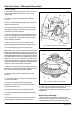
1. Set up dial indicator on back face of crownwheel
(11) as shown in Fig. 14 and screw in each adjusting
nut (16) just sufficiently to ensure that no crownwheel
axial movement is registered on dial indicator.
2. Tap straps (49) and rotate crownwheel, then
re-check that no axial movement is present.
Setting Crownwheel and Pinion Backlash
1. Move dial indicator onto crownwheel (11) tooth as
shown in Fig. 16. Hold pinion (37) still and rock
crownwheel (11) backwards and forwards, to check
free play between gears (backlash), and note variation
of indicator reading.
2. Repeat the above steps three more times so that
four readings are taken at positions equally spaced
around crownwheel (11).
Note: The variations of readings on dial indicator must
be within limits of 0.203 - 0.330 mm
(0.008 - 0.013 in). If difference in backlash of more
than half backlash tolerance exists between tooth
mesh positions, then assembly should be further
examined for cause and rectified.
Checking Crownwheel and Pinion Mesh
1. Apply a thin coating of engineers marking compound
to several consecutive crownwheel teeth.
2. Turn crownwheel for few revolutions in both
directions to make positive tooth contact impression
on crownwheel and pinion teeth.
3. Inspect deposit of marking compound on
crownwheel and pinion teeth and compare them with
Fig. 17.
In all cases, action, (if any) to be taken is shown
below:
Fig. A - Indicates correct mesh. No further action
required.
Fig. B - Indicates pinion and crownwheel are too far out
of mesh. To remedy, move pinion inwards towards
crownwheel. To maintain backlash, move crownwheel
away from pinion in direction of arrow B.
Fig. C - Indicates pinion and crownwheel too far into
mesh. To remedy, move pinion outwards away from
crownwheel. To maintain backlash, move crownwheel
towards pinion in direction of arrow B.
If any action is required, adjust pinion position by
altering the thickness of shims (39) i.e. add shims to
move pinion away from crownwheel and remove shims
to move pinion towards crownwheel.
4. When settings are correct, remove pinion bearing
housing setscrews with washers (32 & 31) then pull off
pinion assembly and lift off shims (39).
5. Thoroughly clean shims (39), also mating face of
pinion housing and gear casing (24 & 40) using Loctite
Superclean Safety Solvent 706 or other suitable
chlorinated solvent.
6. Apply a thin film of Loctite 515 gasket eliminator to
one side of each shim (39) then fit, Loctite side first,
onto housing (24).
7. Similarly coat gear casing mating face (40) with
Loctite 515 gasket eliminator and re-fit pinion assembly
to gear casing, tapping into place with a hide faced
hammer.
8. Secure in position with washer (31) and setscrews
(32). Tighten setscrews progressively using diagonal
selection, until tightened to correct torque 244 - 271
Nm (180 - 200 lbf ft).
Final Assembly of Differential
1. When gears are set correctly, fit new split pins (48)
as shown in Fig. 15.
2. Fit thrust screw (21) into gear casing (40). Tighten
firmly against back face of crownwheel (11). Adjust
thrust screw (21) to provide 0.254 - 0.381 mm (0.010 -
0.015 in) clearance by loosening back 1/8th of a turn
then fit lockwasher and locknut (23 & 22).
3. Tighten locknut (22) then secure in position by
bending lockwasher tabs (23) over locknut flat (22),
also into groove in lockscrew shank.