
Operation and maintenance manual


Section 160-0020
9
SM 2151 6-02
Rear Axle Group - Differential Drive Head
SM - 1186
4. Carefully install two straps and secure with strap
nuts (51) and washers (50). Check the alignment of
matching marks on gear casing (40) legs and straps
(49) to ensure that straps are not transposed.
5. Bearing cups (17) should seat snugly in bores and
adjusting nuts (16) should be free to turn with hand
pressure only, if not, it may be because of cross
threading. Remove and deburr. On no account use
additional pressure i.e. hammer.
6. Tighten strap nuts (51) to a torque of 502 - 542 Nm
(370 - 400 lbf ft).
7. Check freedom of diff bearing adjusting nuts (16) by
unscrewing and refitting, to assist this operation tap
straps (49) lightly on top with a 1 kg (2 lb) hammer
(See Fig. 12).
8. Having checked fit of adjusting nuts (16), remove nuts
and washers (51 & 50) then lift off straps (49), bearing
cups (17) and adjusting nuts (16).
Installing Crownwheel and Differential
Assembly into Gear Casing
1. Hold bearing cups (17) in position on bearing cones
(17A) and place crownwheel (11) and differential
assembly in position in gear casing (40) ensuring
correct meshing of crownwheel and pinion teeth.
2. Install two adjusting nuts (16) onto half threads of
gear casing (40) legs. Re-check freedom of adjusting
nuts on threads.
3. Install two straps (49) followed by nuts (51) and
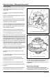
Fig. 15 - Installing Split Pins
Fig. 16 - Setting Dial Indicator onto Crownwheel Tooth
Fig. 13 - Tightening Gear Casing Straps
SM - 1187
Fig. 14 - Setting Dial Indicator on Crownwheel Backface
SM - 1188
VIEWS SHOWING
SPLIT PIN IN POSITION
INSTALL FROM
UNDERNEATH
SM - 1189