
Operation and maintenance manual


Rear Axle Group - Differential Drive Head
8
Section 160-0020
SM 2151 6-02
into differential housing body (13), making sure that
they are free to move vertically in grooves.
6. Similarly, install second pair of clutch plates followed
by mating cage half (9).
Note: The clutch plates and diff cage half must be
assembled as the original matched set to ensure
correct operation of POWR LOK system. If unsure as
to which parts complete a set, measure total thickness
of clutch plates and diff cage half for both sides of
differential unit. Each total thickness figure must be the
same (See Fig. 9).
7. Install wheel (8) into cage half (9) engaging splines
with both friction plates (10) and end face hard against
thrust washer (15).
8. Assemble pinions (7) onto trunnion (20) and lay
assembly in place in cage half (9), in mesh with wheel
(8) as shown in Fig. 10.
9. Add remaining wheel (8) and cage half (9).
10. Stack alternate friction and steel clutch plates
(10 & 44) then check that diff cage half (9) and clutch
plates will slide in differential housing body (13) by
raising and lowering diff wheel (8).
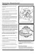
11. If originally fitted, place shims on end face of
differential housing body (13). Install second thrust
washer (15) onto wheel (8) then carefully offer end
flange (46) to the assembly, lining up matching marks
(See Fig. 11).
12. Secure assembly with nuts (47) then tighten nuts to
a torque of 61 - 66 Nm (45 - 49 lbf ft).
13. To check assembly of differential unit, insert a
driveshaft to engage with each wheel (8). Hold one
driveshaft to lock wheel; the other must turn freely.
14. Press a bearing cone (17A) onto each end flange
(14 & 46) until hard against shoulder.
Initial Preparation Before Installing
Assembled Differential Unit
Note: Secure the crownwheel and gear casing
assembly in a suitable diff build stool.
Check fit of adjusting nuts (16) as follows:
1. Clean and deburr gear casing (40) legs and
straps (49).
SM - 2740
Fig. 11 - Differential Assembly
SM - 1185
2. Install bearing cups (17) into half bores of gear
casing (40) legs followed by diff bearing adjusting nuts
(16).
Fig. 12 - Checking Freedom of Diff Bearing Adjusting Nut