
Operation and maintenance manual


Rear Axle Group - Differential Drive Head
6
Section 160-0020
SM 2151 6-02
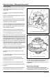
2. Secure assembly in vice, hold on coupling flange
(33).
3. Secure length of cord around pinion bearing cage
(24) and attach free end to spring balance.
4. Pull tangentially on spring balance to rotate pinion
bearing cage. Note the force required to maintain
rotation, ignoring initial starting force.
5. The correct spring balance reading should be
between 3.5 - 6 lbs pull (1.5 - 2.75 kg) giving a rolling
torque of 15 - 25 lbf in (1.7 - 2.8 Nm).
If torque reading is less than 1.7 Nm (15 lbf in) then a
smaller outer spacer needs to be fitted.
If torque obtained is greater than 2.8 Nm (25 lbf in) then
a larger outer spacer needs to be fitted.
Note: If largest available combination of spacers (26 &
27) is already fitted, then a defect must be present in
one or more parts of the assembly and needs to be
found and remedied before continuing differential build.
6. When correct pre-load has been achieved, remove
coupling flange nut (34) and pull off coupling flange
(33).
7. Fit a new oil seal (29) into pinion end cap (30) with
spring loaded lip facing inboard when fitted on axle,
taking care not to damage the seal.
8. Pack cavity between seal lips with Duckhams
Keenomax L2 or equivalent grease.
9. Apply Red Hermetite or similar sealant to both faces
of pinion end cap joint (25) then assemble onto bearing
housing flange (24) along with pinion end cap assembly
(29 & 30).
Note: For assemblies where no joint is fitted, clean
mating faces with Loctite Superclean Safety Slovent
706 or similar chlorinated solvent then apply a
continuous bead of Loctite Gasket Eliminator 515 to
one of mating faces prior to assembly.
10. Secure end cap centrally in position about pinion
(37) with washers and setscrews (31 & 32). Tighten
setscrews to 180 - 200 lbf ft (244 - 271 Nm).
11. Refit coupling flange (33) and nut (34). Torque
tighten nut (34) to 800 - 900 lbf ft (1085 - 1220 Nm).
12. Lock nut (34) in position by peening a portion of nut
locking ring into slot in pinion shank (37).
Fig. 6 - Tightening Pinion Nut
SM - 2737
SM - 2738
Setting Pinion Depth
1. If original crownwheel and pinion (11 & 37) are being
refitted, place the already assembled pinion unit (24 to
38) into bevel casing (40), having fitted original shims
(39) between pinion bearing housing (24) and bevel
casing (40). See Fig. 8.
2. Fit pinion bearing housing setscrews and washers
(32 & 31) to secure pinion bearing housing (24) to bevel
casing (40) then tighten to 180 - 200 lbf ft (244 - 271
Fig. 7 - Method Of Setting Bearing Pre-load