
Operation and maintenance manual


Section 160-0020
5
SM 2151 6-02
Bevel Pinion
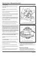
1. If new nose bearing (38) is to be fitted, apply a light
coating of Loctite 641 to bore of nose bearing then
press onto pinion (37) hard against its abutment
shoulder. To retain bearing, lightly peen over end of
pinion shaft in three places as shown in Fig. 5.
2. Press inner and outer pinion cups (35 & 36) into
pinion bearing housing (24) until they register hard and
square against abutment shoulders.
3. Press inner pinion bearing cone (36A) onto pinion
shaft (37). Lightly oil bearing cone with clean gear oil.
4. Fit inner bearing spacer (26) followed by outer
spacer (27) onto pinion shaft (37) then feed assembly
into housing (24).
Note: If new parts are being fitted, install the largest
available spacers. This is to ensure that the bearing
cannot be over pre-loaded, preventing bearing damage.
5. Press outer pinion bearing cone (35A) into position
on pinion (37) then lightly oil with clean gear oil.
Setting Pinion Bearing Pre-Load
1. Fit coupling flange washer (28) onto pinion (37)
followed by coupling flange (33) and pinion nut (34). Do
not install end cap (30) at this stage. Secure assembly
in vice then tighten pinion nut as shown in Fig. 6 to a
torque of 800 - 900 lbf ft (1085 - 1220 Nm).
Check and if necessary adjust pinion bearings pre-load
as follows (see Fig. 7).
Rear Axle Group - Differential Drive Head
setting shims (39).
Note: If the original pinion and crownwheel are to be
reinstalled, retain the shim pack as a unit for reuse.
2. Remove all traces of sealant from the outer shims
(39), pinion bearing housing (24) and gear casing (40).
3. Secure pinion assembly in a vice fitted with soft
jaws then remove pinion nut (34).
4. Pull off coupling flange (33), using suitable
extraction equipment.
5. Lift off pinion end cap (30) complete with pinion oil
seal (29), followed by coupling flange washer (28).
6. Tap pinion (37) along with inner bearing cone (36A),
pinion spacers (26 & 27) and pinion nose bearing (38)
out of bearing housing (24). Remove spacers, inner
bearing cone and nose bearing from pinion if required.
7. Lift out outer bearing cone (35A) from bearing
housing (24). Bearing cups (35 & 36) can now be
drifted out of bearing housing (24) for replacement if
required.
Note: If either bearing cup or cone need replacing, they
must be replaced as a set.
8. Prise out and discard pinion oil seal (29) from pinion
end cap (30).
ASSEMBLY
Numbers in parentheses refer to Fig. 1.
Note: Prior to assembly, lightly oil bearings in clean
gear oil as specified in Section 300-0020,
LUBRICATION SYSTEM.
WARNINGS
To prevent personal injury and property
damage, be sure wheel blocks, blocking
materials and lifting equipment are properly
secured and of adequate capacity to do the job
safely.
When necessary to drive on components
during assembly, be sure to use a soft drift to
prevent property damage and personal injury.
SM - 2736
Fig. 5 - Peening Pinion Nose Bearing
PEEN IN
THREE
PLACES