
Operation and maintenance manual


Section 160-0020
3
SM 2151 6-02
Rear Axle Group - Differential Drive Head
SM - 033
12. Unscrew and remove oil filler/level plug (55) and
drain plug (54) to drain oil from drive head.
Driveshafts
1. Remove bolts (4, Fig. 2) and washers (3, Fig. 2).
2. Using suitable lifting equipment, pull off planet
carrier assembly (8, Fig. 2) and place on bench, small
diameter down.
3. Pull out driveshaft assembly (1, Fig. 2) from hub to
disengage the shaft splines from wheel (8).
4. Cover open end of hub unit to prevent entry of dirt.
5. Repeat steps 1 through 4 for other hub end.
Drive Head Unit from Axle Casing
1. If gear casing (40) is not in vertical position, fit two
'U' bolts to coupling flange (33) and using lifting gear,
rotate the axle. Leave lifting gear in position.
2. Remove nuts (41) and spring washers (42).
3. Carefully remove gear casing (40) assembly clear of
axle casing (6) and place on a suitable build stool.
4. Remove all traces of gasket material from axle
casing (6) and gear casing (40) flanges.
5. Remove lifting gear and 'U' bolts from coupling
flange (33).
DISASSEMBLY
Numbers in parentheses refer to Fig. 1.
WARNING
To prevent personal injury and property
damage, be sure wheel blocks, blocking
materials and lifting equipment are properly
secured and of adequate capacity to do the job
safely.
When necessary to drive out components
during disassembly, be sure to use a soft drift
to prevent property damage and personal
injury.
Differential Unit
1. Straighten lockplate tabs (23) then loosen crownwheel
thrust screw locknut (22) and remove thrust screw (21),
locknut and washer from gear casing (40).
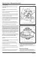
Fig. 2 - Part View of Hub Reduction Unit
7 - Oil Filler/Level Plug
8 - Planet Carrier
1 - Driveshaft Assembly
2- Hub
3 - Washer
4- Bolt
5 - Washer
6- Bolt