
Operation and maintenance manual


Section 140-0060
13
SM 2148 5-02
6. Install differential drain plug (48) and tighten.
7. Add gear oil of the type specified in Section 300-0020,
LUBRICATION SYSTEM, through oil filler/level hole until
the oil is level with bottom of filler/level hole.
8. Check oil level to bottom of filler/level hole in both
hubs and top up as necessary. Leave oil to settle for
15 minutes then check oil level again in both hubs and
drive head. Always check final oil level at drive head.
9. Install then tighten filler/level plugs in drive head and
both hubs.
10. Install front axle onto vehicle. Refer to Section 180-
0020, FRONT SUSPENSION.
11. Install driveline between differential shaft (43)
flange and transmission flange. Tighten driveline
capscrews to a torque of 154 Nm (113 lbf ft). Refer to
Section 130-0010, FRONT DRIVELINES.
12. Install breather tube (49) in adaptor (74).
13. Clean interfaces between road wheels, hub and
wheel nuts.
14. Re-fit road wheels, securing with wheel nuts.
Remove stands or timber supports and lower vehicle to
ground. Fully tighten wheel nuts to a torque of 365 -
400 lbf ft (495 - 542 Nm).
15. Remove wheel blocks.
MAINTENANCE
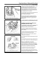
Numbers in parentheses refer to Fig. 1, unless
otherwise specified.
WARNING
To prevent personal injury and property
damage, be sure wheel blocks, blocking
materials and lifting equipment are properly
secured and of adequate capacity to do the job
safely.
General
At first service, then every 1 000 hours (6 months),
check the following and repair or replace where
necessary:
a - Input flange for wear/damage.
b - Pinion oil seals for leaks.
c - Breather for signs of leakage or dirt ingress.
Front Axle Group - Differential Drive Head
f. The oil seal lip or journal of coupling should be
smeared with clean gear oil prior to assembly. If seal is
fitted dry, it can burn out in a matter of minutes, before
oil reaches it.
2. Install end cap (42) assembly onto differential
shaft (43).
3. Apply a small bead of Hylomar sealant around
corner of bearing recess in end cap (42) and axle
casing (37).
4. Install shaft bearing (40), lockplate (39) and left
hand threaded shaft nut (38) onto differential shaft
(43). Tighten shaft nut (38) so that shaft bearing (40) is
hard against abutment shoulder on differential shaft
(43), then bend over lockplate tab to fasten shaft nut
(38) in position.
5. Check security of rear end cap studs (46) in axle
casing (37) and tighten to a torque of 26 - 28 Nm
(19 - 21 lbf ft) if necessary.
6. Install differential shaft (43) into axle casing (37)
carefully engaging shaft splines with helical pinion (8)
bore splines. When differential shaft is correctly
located, drive it home using hide faced hammer.
7. Install spring washers (45) and nuts (44) evenly
tightening to a torque of 38 - 43 Nm (28 - 32 lbf ft).
Note: Check that there is a gap of 0.2 mm (0.008 in)
maximum between joint faces of end cap (42) and axle
casing (37). There must be NO PRE-LOADING of
shaft bearing (40).
Final Assembly
1. Carefully feed driveshaft assembly (1, Fig. 2) back
into axle casing to locate driveshaft splines in
wheel (30).
2. Coat hub mating face of planet carrier (8, Fig. 2)
with Loctite 275 then offer planet carrier unit to hub
(2, Fig. 2) using suitable lifting gear if required. Ensure
planet gear teeth mesh with sun gear.
3. Install bolts (4, Fig. 2) and washers (3, Fig. 2) then
tighten to a torque of 149 -164 Nm (109 - 121 lbf ft).
4. Install bolt (6, Fig. 2) and washer (5, Fig. 2) then
tighten to a torque of 237 - 244 Nm (175 - 180 lbf ft).
5. Rotate both hubs until bottom of oil filler/level plug
holes are approximately 13 mm (0.5 in) above axle
centre line (level with oil filler/level hole).