
Operation and maintenance manual


Front Axle Group - Differential Drive Head
12
Section 140-0060
SM 2148 5-02
(5). Add 0.076 mm (0.003 in) to measured gap to
obtain correct shim (4) pack thickness, providing end
play for helical pinion bearings.
12. Remove setscrews (1) and bearing retainer (3).
13. Place selected shim (4) pack on helical gear
housing (5) and install bearing retainer (3), spring
washers (2) and setscrews (1). Evenly tighten
setscrews to a torque of 60 - 65 Nm (44 - 48 lbf ft).
14. Place completed assembly in clean storage place
until required for installing into axle.
Note: If the period before lifting the assembled unit
into the axle is likely to be more than 4 hours,
thoroughly oil all gears and bearings. If it is to be more
than 12 hours, the oil should be of a protective type,
with anti-rust additive such as Shell 'Ensis 40' and the
unit should be stored in a dust proof and damp proof
container.
INSTALLATION
Numbers in parentheses refer to Fig. 1, unless
otherwise specified.
WARNING
To prevent personal injury and property
damage, be sure wheel blocks, blocking
materials and lifting equipment are properly
secured and of adequate capacity to do the job
safely.
Drive Head Unit into Axle Casing
1. Check studs (50) and replace as necessary.
Tighten studs (50) to a torque of 90 - 100 Nm
(66 - 74 lbf ft).
2. Apply a thin coating of Red Hermatite to axle casing
(37) gasket face and install gasket (36).
3. Using suitable lifting equipment, offer drive head
unit to axle casing (37) ensuring that drive head is in
correct position, with matching marks lined up.
4. Install spring washers (56) and nuts (57) then tighten
nuts to a torque of 230 - 258 Nm (170 - 190 lbf ft).
Differential Shaft
1. Fit oil seal (41) into rear end cap (42) noting the
following:
SM - 1193
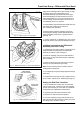
a. Seal must be fitted using oil seal bumper tool (See
Special Tools), which bears on the seal close to its
outside diameter where the casing is strongest. Failure
to use the oil seal bumper tool will result in distortion of
seal casing, uneven wear of lip and leakage. Fig. 17
illustrates typical example where the seal is fitted into
the seal retainer.
b. Seal must remain square to the bore during fitting. If
seal cocks over and one side enters the bore first, it
will almost certainly result in distortion of the casing
which will not be corrected by straightening up the seal
further down the bore. Where possible the seal should
be fitted under a press, which reduces the likelihood of
this problem.
c. Seal must be truly square after fitting, a cocked seal
will act as an oil pump.
d. When replacing a seal, always check differential shaft
(43) surface for damage in region polished by oil seal lip;
even slight damage in this area can cause leakage. Very
slight marks may be polished out with fine emery cloth but
it is essential that polishing marks are parallel to the seal
lip. Where there is more serious damage, it is permissible
to fit two seals back to back if there is room in the retainer,
i.e. outer seal with spring facing inwards. The outer seal
acts as a spacer and ensures that inner seal is fitted
square and that it runs on a different part of coupling
surface.
e. Pack the seal with high temperature grease before
fitting.
BEFORE
FITTING
AFTER
FITTING
BUMPER
TOOL
SEAL
HOUSING
OIL
SEAL
OIL
SEAL
Fig. 17 - Method of Fitting Oil Seal