
Operation and maintenance manual


Front Axle Group - Differential Drive Head
10
Section 140-0060
SM 2148 5-02
In all cases, action, (if any) to be taken is shown
below:
Fig. A - Indicates correct mesh. No further action
required.
Fig. B - Indicates pinion and crownwheel are too far
out of mesh. To remedy, move pinion inwards towards
crownwheel. To maintain backlash, move crownwheel
away from pinion in direction of arrow B.
Fig. C - Indicates pinion and crownwheel too far into
mesh. To remedy, move pinion outwards away from
crownwheel. To maintain backlash, move crownwheel
towards pinion in direction of arrow B.
If any action is required, adjust pinion position by
altering the thickness of shims (62) i.e. add shims to
move pinion away from crownwheel and remove
shims to move pinion towards crownwheel.
Helical Pinion/Helical Housing Assembly
1. Press inner bearing cup (9) into gear casing (17).
2. Press helical bearing cones (9A & 7A) onto helical
pinion (8).
3. Place helical pinion (8) in position on gear
casing (17).
4. Install dowels (16) into their relevant holes in gear
casing (17).
5. Apply a thin coating of Red Hermatite to helical
housing clamping face on gear casing (17) and install
gasket (15) in position.
6. Install helical gear housing (5) onto gear casing (17)
ensuring correct location with dowels (16).
7. Install bolts (69) and washers (68) and tighten bolts
to a torque of 98 - 109 Nm (72 - 80 lbf ft).
8. Install outer bearing cup (7) onto its bearing cone
(7A) already on helical pinion (8).
9. Install bearing retainer (3) on helical gear housing
(5) and secure with two opposite setscrews (1). Hand
tighten setscrews (1) at this point.
10. Shock load helical pinion bearings with hide faced
hammer.
11. Using feeler gauges, measure gap between joint
faces of bearing retainer (3) and helical gear housing
SM - 1189
4. Set up dial indicator on crownwheel (25) and check
for no end float condition.
Setting Crownwheel and Pinion Backlash
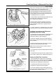
1. Move dial indicator onto crownwheel (25) tooth as
shown in Fig. 15. Hold pinion (13) still and rock
crownwheel (25) backwards and forwards, to check
free play between gears (backlash), and note variation
of indicator reading.
2. Repeat the above steps three more times so that
four readings are taken at positions equally spaced
around crownwheel (25).
Note: The variations of readings on dial indicator must
be within limits of 0.203 - 0.330 mm
(0.008 - 0.013 in). If difference in backlash of more
than half backlash tolerance exists between tooth
mesh positions, then assembly should be further
examined for cause and rectified.
Checking Crownwheel and Pinion Mesh
1. Apply a thin coating of engineers marking
compound to several consecutive crownwheel teeth.
2. Turn crownwheel for few revolutions in both
directions to make positive tooth contact impression
on crownwheel and pinion teeth.
3. Inspect deposit of marking compound on
crownwheel and pinion teeth and compare them with
Fig. 16.
Fig. 15 - Setting Dial Indicator onto Crownwheel Tooth