
Operation and maintenance manual


Section 140-0060
9
SM 2148 5-02
Front Axle Group - Differential Drive Head
SM - 1186
alignment of matching marks on gear casing (17) legs
and straps (33) to ensure that straps are not
transposed. Bearing cups (24) should seat snugly in
bores and adjusting nuts (23) should be free to turn
with hand pressure only, if not, it may be because of
cross threading. Remove and deburr. On no account
use additional pressure i.e. hammer.
5. Install washers (34) and temporarily install plain nuts
onto studs (55). Tighten nuts to a torque of
502 - 542 Nm (370 - 400 lbf ft).
6. Check freedom of bearing adjusting nuts (23) by
unscrewing and refitting, to assist this operation tap
straps (33) lightly on top with a 1 kg (2 lb) hammer
(See Fig. 11).
7. Having checked fit of adjusting nuts (23), remove
straps (33), bearing cups (24) and adjusting nuts (23).
Installing Crownwheel and Differential
Assembly into Gear Casing
1. Hold bearing cups (24) in position on bearing cones
(24A) and place crownwheel (25) and differential
assembly in position in gear casing (17).
2. Install two adjusting nuts (23) onto half threads of
gear casing (17) legs. Re-check freedom of adjusting
nuts on threads.
3. Install two straps (33) onto studs (55) to locate on
bearing cups (24) and adjusting nuts (23).
Note: Ensure matching marks coincide to prevent
misalignment of straps (33).
4. Turn adjusting nuts (23) hand tight against bearings
(24 & 24A).
5. Install washers (34) and nuts (35). Tighten nuts to a
torque of 502 - 542 Nm (370 - 400 lbf ft) (See Fig. 12).
Setting ‘No End Float’ Condition
1. Set up dial indicator on back face of crownwheel
(25) as shown in Fig. 13 and screw in each adjusting
nut (23) just sufficiently to ensure that no crownwheel
axial movement is registered on dial indicator.
2. Tap straps (33) and rotate crownwheel, then
re-check that no axial movement is present.
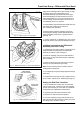
3. Turn each adjusting nut (23) until nut slots line up
with one of the two split pin holes in straps (33). Install
two split pins (51) as shown in Fig. 14.
Fig. 14 - Installing Adjusting Nut Split Pins
VIEWS SHOWING
SPLIT PIN IN POSITION
INSTALL FROM
UNDERNEATH
Fig. 12 - Tightening Gear Casing Straps
SM - 1187
Fig. 13 - Setting Dial Indicator on Crownwheel Backface
SM - 1188