Copyright © Terabee 2017 Installation and Operation Manual Firmware 1.0.0 Technical Specifications: Principle: Infrared laser Time-of-Flight (ToF) Range: Up to 1.2m indoors Update rate: 50Hz (divided by the number of sensors used) Range resolution: 1mm Accuracy: ± 6cm Field of view: Approx. 20° Supply voltage: 5V DC Supply current: 50mA peak Interfaces: USB 2.0 Micro-B UART, +3.3V level, 115200 baud I2C, +3.
Copyright © Terabee 2017 Table of Contents 1 About the TeraRanger Multiflex 1.1 Inside the Package 1.2 Safety Note 1.3 Dimensions and Mounting 1.4 Details on Supply Voltage 1.5 About the Connector 1.6 UART Data Interface (default) 1.7 I2C Data Interface 1.8 USB Interface 1.9 Normal Operation 2 Assembly 3 Connecting the TeraRanger Multiflex Using a Computer with a Serial Console 3.1 Windows 3.2 MacOS 3.3 Linux 4 UART & USB Protocol Description 4.1 Basic Commands (UART & USB) 4.2 Printout Modes 4.
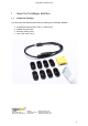
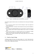
Copyright © Terabee 2017 1 About the TeraRanger Multiflex 1.1 Inside the Package You will receive the following items when purchasing the TeraRanger Multiflex: ● ● ● ● 8 assembled sensors with covers + 4 extra covers Multiflex Hub with case 8 flat flex cables (10cm) Micro USB cable (50cm) Terabee 90 Rue Henri Fabre 01630 Saint-Genis-Pouilly Website: Technical support: Commercial: www.teraranger.com support@teraranger.com teraranger@terabee.
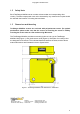
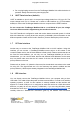
Copyright © Terabee 2017 1.2 Safety Note Each TeraRanger Multiflex sensor contains a laser emitter and corresponding drive circuitry. The laser output power must not be increased by any means and no optics should be used with the intention of focusing the laser beam. 1.3 Dimensions and Mounting TeraRanger Multiflex sensors are enclosed with polycarbonate covers.
Copyright © Terabee 2017 Figure 2: TeraRanger Multiflex sensor dimensions in millimeters The following aspects should be taken into consideration when mounting the TeraRanger Multiflex: ● ● ● ● ● 1.4 Do not remove the plastic covers as this will misalign the optics and degrade the sensor’s performance. Sensors should not be connected or disconnected from the strip while the Multiflex is powered. Do not mount the TeraRanger Multiflex Hub onto hot surfaces or near other sources of heat.
Copyright © Terabee 2017 1.5 About the Connector The TeraRanger Multiflex Hub connects to your equipment using a 7-pin connector from the Hirose DF13 series. (The part number of the corresponding female connector is DF13-7S-1.25C.) The TeraRanger Multiflex does not ship with a connector cable, but we recommend purchasing the female connector here. Please use Figure 3 and following table to identify the pins: Figure 3.
Copyright © Terabee 2017 ● 1.6 Do not plug/unplug sensors from the TeraRanger Multiflex Hub while the device is powered. Always disconnect the power supply first! UART Data Interface (default) UART is available on pins 5 and 6. It accepts input voltage levels from 3.3V up to 5V. The output voltage level is 3.3V. Please use a serial to USB interface (e.g. FTDI breakout boards) to connect the TeraRanger Multiflex Hub to a computer via the UART interface.
Copyright © Terabee 2017 installation, unplug the interface for a moment and plug it back in. The virtual COM port should now be available on your PC. Note: Do not plug and/or unplug the sensor units while the TeraRanger Multiflex is powered by a computer. Disconnect the USB cable first! 1.9 Normal Operation Each time the TeraRanger Multiflex Hub is powered, the GREEN LED will turn on. At the same time, the Hub will detect how many sensors are connected.
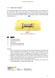
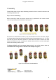
Copyright © Terabee 2017 2 Assembly Please follow these 5 simple steps illustrating a tutorial on how to connect 8 sensors to the TeraRanger Multiflex Hub. Step 1. Sensor Positioning Before connecting, make sure that the sensors are (1) positioned in the correct numeric order and (2) facing the same direction. See Figure 5. Figure 5. Sensor ascending numeric order Each sensor is marked with a number (1 to 8), and a direction arrow for connection (Figure 5).
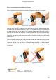
Copyright © Terabee 2017 Step 2. Connecting the Flex Cable to the sensor Start by plugging the Flex Cable to the sensor’s Flexible Flat Cable (FFC) connector. Figure 7. Open, Insert, Close Note that each of the FFC connectors need to be manually opened and then closed when connecting the Flex Cables as shown in Figure 7. For easier opening you can gently pull the small locking ‘tabs’ on the sides of the connector before pulling the connector down. You may find this easier with tweezers.
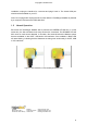
Copyright © Terabee 2017 Step 3. Connecting sensors to each other Continue to connect all 8 sensor units together respecting their assigned numerical order (Figure 9). Figure 9. Correct connection of 8 sensor units Step 4. Joining the strip of sensors to TeraRanger Multiflex Hub Connect the strip of 8 sensors to the TeraRanger Multiflex Hub (Figure 10). The Hub also contains an FFC connector, hence we ask to respect the guidelines on connecting as described in Step 2. Figure 10.
Copyright © Terabee 2017 Step 5. Ready to test! Once fully assembled, the TeraRanger Multiflex is ready for testing on your computer (Figure 11). Use the micro USB cable (provided in the package) to connect the TeraRanger Multiflex Hub with a computer. Figure 11. TeraRanger Multifex assembled Terabee 90 Rue Henri Fabre 01630 Saint-Genis-Pouilly Website: Technical support: Commercial: www.teraranger.com support@teraranger.com teraranger@terabee.
Copyright © Terabee 2017 3 Connecting the TeraRanger Multiflex Using a Computer with a Serial Console TeraRanger Multiflex can interact with any serial console using the following configuration, both for USB, UART and I2C interfaces: 115200 bit/s, 8 data bits, no parity bit and one stop bit. 3.1 Windows In Windows you can use terminal emulation software of your choosing, however we suggest you use HTerm (http://www.der-hammer.info/terminal/).
Copyright © Terabee 2017 Figure 13. H-Term Main Interface To communicate with the terminal emulation software, you need to send a command in hexadecimal via the “Type” box. First check the “Hex” checkbox and choose the “HEX” Type. Figure X gives the example of the command which allows data to be shown in TEXT mode when 8 sensor units are used. Please see Section 4.1 for basic commands! 3.2 MacOS In MacOS we recommend to use a serial port terminal application such as CoolTerm (http://freeware.
Copyright © Terabee 2017 Figure 15. Serial Port Setup After, in the “Terminal Tab” (Figure 16) make sure the following fields are selected: 1. Terminal Mode: Raw Mode 2. Enter Key Emulation: CR+LF Once done, click “OK” to apply changes. Figure 16. Terminal Setup In the toolbar, click the “Connect” button to start the data stream. Terabee 90 Rue Henri Fabre 01630 Saint-Genis-Pouilly Website: Technical support: Commercial: www.teraranger.com support@teraranger.com teraranger@terabee.
Copyright © Terabee 2017 Figure 17. Sending commands To send commands, in the Menu bar click “Connection” and after “Send string” (shortcut: cmd+T) as shown in Figure 17. Select the “Hex” option as the commands are given in hexadecimal values. See Section 4.1 for basic commands! Figure 18. Sending hexadecimal values. You can find more information about using CoolTerm at the following address: https://learn.sparkfun.com/tutorials/terminal-basics/coolterm-windows-mac-linux 3.
Copyright © Terabee 2017 2. sudo apt-get install cutecom 3. cutecom The application automatically runs after launching the command “cutecom”. Next, enter the corresponding Device name by sending the following command in your Linux shell window: ls /dev/tty* The device name is usually /dev/tty/ACM0 or /dev/tty/ACM1. Figure 19. Recognizing Device Name In the main interface, make sure to fill the following fields (Baudrate, Data Bits, Parity, Stop Bits) as shown in Figure 20. Figure 20.
Copyright © Terabee 2017 To send commands, the TeraRanger Multiflex uses a Python script. Please follow the ReadMe file (available also under Support section on www.teraranger.com) from the Python script to send the commands. 4 UART & USB Protocol Description 4.
Copyright © Terabee 2017 4.2 Printout Modes TeraRanger Multiflex firmware supports two printout modes which can be selected by sending the corresponding hexadecimal command to the Multiflex using the serial terminal application (See Section 3 for detailed instructions). Please note that the default mode is binary.
Copyright © Terabee 2017 - New line character: \n (10 decimal / 0x0A hex) *if a sensor is not connected or the interface board is unable to obtain a distance measurement from the sensor, the associated distance value is replaced by -1 4.3 Configuring TeraRanger Multiflex Sensors All commands are a series of bytes.
Copyright © Terabee 2017 The “Header” and the “Command name” byte values remain always the same: 00 52 03, despite the amount of sensors used in an application! The following 3 steps provide guidelines on how to calculate the remaining “Sensor Mask” and “CRC” byte values: 1. Calculate the binary byte of operating sensors Figure 22. Calculating the Binary Byte value The binary byte consists of 8 values, that represent operating (1) and non-operating (0) sensors.
Copyright © Terabee 2017 3. Calculate the CRC byte of the command by using the CRC byte calculator Figure 23. Calculating the CRC byte value First enter the CRC polynomial bit sequence, which is always: 100000111. Second, enter the Message Contents, which we have determined before: 00 52 03 D3. Third, click on “Calculate” to acquire the CRC byte, which in this case is FA. See Figure 23 for visual instructions. Finally, we have obtained the full command for configuring the sensor units.
Copyright © Terabee 2017 5 I2C Protocol Description The TeraRanger Multiflex by default comes in I2C base address (7 bit) 0x55. Same as when using UART mode, the Multiflex is free running, which means that it will restart a new measurement as soon as the last one is finished. The displayed data via I2C protocol is always updated at the end of a measurement. Nevertheless, it can always be read at any time.
Copyright © Terabee 2017 Header Command Description 0x00 Ask for READING Write this value to Multiflex via I2C and read the distance frame. It is 18 byte long. 8*two bytes for the sensor distances+the index of the sensor from which the last distances has been received + one CRC byte.
Copyright © Terabee 2017 Figure 24. Dynamic reconfigure To activate desired sensors set up bit mask by enabling check boxes (Figure 24). Terabee 90 Rue Henri Fabre 01630 Saint-Genis-Pouilly Website: Technical support: Commercial: www.teraranger.com support@teraranger.com teraranger@terabee.