User Manual for TeraRanger Evo 64px with: USB and UART backboard Technical support: support@teraranger.com Sales and commercial support: teraranger@terabee.
Table of contents: 1 Introduction 3 2 Mechanical integration 3 2.1 Mechanical design 4 2.2 Sensor handling during system assembly 3 USB backboard use 4 5 3.1 Graphical User Interface 5 3.1.2 Basic Operation 5 3.1.1 Prerequisites 5 4 UART backboard use 11 4.2 Backboard LEDs 12 4.1 UART interface 11 4.3 Electrical characteristics 12 5 Communication 13 5.1 UART protocol information 13 5.2 USB protocol information 13 5.3 Commands 13 5.
1 Introduction The purpose of this document is to give guidelines for use and integration of the TeraRanger Evo 64px multi-pixel sensor with (a) UART backboard, and/or (b) USB backboard using these standard communication interfaces. 1.1 About TeraRanger Evo 64px TeraRanger Evo64px is the multi-pixel Time-of-Flight sensor of the TeraRanger Evo product family. It provides a matrix of 8x8 distance readings over a 15 degrees FOV, with a maximum range up to 5m.
● ● ● ● It is advisable to avoid having other sources of Continuous Wave or modulated IR light close to the sensor Please consider that dust, dirt and condensation can affect the sensor’s performance It is not advised to add an additional cover in front of the sensor Drone rotor blades, or other environments with flickering (‘chopped’) ambient light in the field of view can affect the sensor’s readings 2.1 Mechanical design Figure 2. TeraRanger Evo 64px external dimensions 2.
3 USB backboard use The USB backboard comes with a standard Micro-USB connector. 3.1 Graphical User Interface A free Graphical User Interface (GUI) is available, providing an easy way to visualize the data from your TeraRanger Evo 64px sensor. This is useful for demonstration, testing purposes and checking some of the basic parameters of the sensor. It also provides a way to easily export raw distance data and upgrade the firmware running on the device.
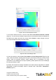
Figure 3. Windows protection screen during installation After successful installation, make sure your TeraRanger Evo 64px is connected to a USB port on your computer. In the GUI select File > Connect (Ctrl+O). You will immediately see 64 distance readings displayed in a 8x8 pixel color map, labeled Depth Map (Figure 4). Figure 4. Graphical user interface: home screen On the right side of the depth map you will find a color vs distance (millimeters) scale.
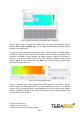
Figure 5. Auto vs manual distance bounds To set custom distance bounds, in the GUI select File > Auto Distance Bounds > Disable (Figure 5). You should now be able to input minimum and maximum bounds in millimeters in the fields on the bottom left side of the screen. Select “Adjust” to apply changes, and your color map will adjust according to the set values. Figure 6. Fast vs Close Range mode On the main interface, select between Fast mode and Close Range mode (Figure 6).
Figure 7. Interpolate vs discrete mode The GUI also offers the option to display the distance data in a 3 dimensional map representation. Select File > View > 3D Plot, and a new window will now open with the 64 pixels represented in a 3D model. Choose to demonstrate the 3D model in a Plane or Mesh view (Figure 8), both options can be selected at the bottom of the main GUI screen. Figure 8.
Figure 9. Stream raw distance and ambient values in real-time You can also choose to visualize the ambient values in an 8x8 pixel grayscale map by selecting File > View > Ambient map. This can be useful in detecting other near-infrared sources in your environment. You can also export raw distance and ambient data in a text-format file, by selecting “Save” on the main screen of the GUI. Next, you’ll be asked to save the text file in a location of your preference.
Figure 11. Text file of raw data exported from GUI Once you are done with testing the sensor, in the GUI select File > Disconnect (Ctrl+D), the GUI will terminate its VCP connection with the sensor. 3.1.3 Firmware Upgrade It is possible to upgrade the firmware running on your device if a new firmware version is made available on the Terabee website. The current firmware version on your TeraRanger Evo can be found by selecting Help > About in the graphical user interface.
4 UART backboard use 4.1 UART interface The TeraRanger Evo 64px can be controlled through UART interface. It uses a single 9 pin Hirose DF13 connector for interfacing to the host system. The mating connector is a Hirose DF13-9S-1.25C with crimping contacts DF13-2630SCF (tin) or DF13-2630SCFA (gold).
4.2 Backboard LEDs Five LEDs are mounted to give visual feedback on the sensor. Table below lists the functionality of each LED: LED Description PWR (orange) Power indicator, on when 5V connected Rx/Tx (red/green) UART receive and transmit indicators LED 0 / LED 1 For internal use only 4.3 Electrical characteristics DC electrical characteristics Power supply Interface logic levels (referenced to +3V3) Parameter Minimum Standard Maximum Voltage input 4.75 V 5V 5.
5 Communication 5.1 UART protocol information The UART communication for the TeraRanger Evo 64px uses a simple protocol via UART depending on the backboard used with the sensor. The communication parameters for UART are: Baud Rate: 3000000 Data Bits: 8 Stop Bit(s): 1 Parity: None HW Flow Control: None 5.2 USB protocol information The USB communication for the TeraRanger Evo 64px uses a simple protocol via USB depending on the backboard used with the sensor.
The table below lists the commands, including address and CRC-8, that can be sent to the sensor: Command Name Command Description Command Distance Print The sensor outputs 64 distance values 0x00 11 02 4C Distance Ambient Print (Default) The sensor outputs 64 distance values and 64 ambient values 0x00 11 03 4B Close Range Mode The sensor takes 2 subsequent frames at different light modulation frequencies and builds the final image by picking the best pixels of the 2 frames.
Depending on the mode, each frame will output one or more data packets with each packet identified by a header, for example in Distance & Ambient mode, the sensor will output two frames containing 64 distance values and 64 ambient values followed by a CRC32 to secure the data integrity on the transmission. The output format structure in Distance mode is depicted in Figure 13. Figure 13. Evo 64px output format structure The frame transmission ends with a New Line character (1 byte).
For data output structure please reference table below. Header Description Structure 0x11 / 0d17 Distance: 64 distance measurements as calculated by the sensor for each pixel after temperature, ambient light and distance correction. 14 bit integer * 64 * 2 Each pixel distance value is transmitted as two bytes, representing the hibyte and the lobyte of the pixel value. Hibyte first and lobyte second. The MSB of each byte should be cleared to zero.
frame, a pixel can be in one of four states. Please consult table below for possible measurement output. Measurement status* Output Valid Measurement (equivalent to distances from 100mm to 5000mm) 0x0064 - 0x1388 Object too close (below minimum distance) 0x0000 Object too far (above maximum distance) 0x3FFF ERROR (unable to give back value, eg.
Appendix A.1 CRC validation When using python, you will find a dedicated module named ‘crcmod’. Please install the module using ‘pip’ with the following command: pip install crcmod A.1.1 How to calculate CRC8 checksum for Evo 64px After defining this function: self.crc8 = crcmod.predefined.mkPredefinedCrcFun('crc-8') You will be able to use the above function on any buffer, as illustrated in the code below. In this case ‘ack’ variable is a 4-byte buffer containing an ACK response. crc = self.
crc_value |= (ord(frame[index + 7]) & 0x0F) crc_value = crc_value & 0xFFFFFFFF crc32 = self.crc32(frame[:index]) if crc32 == crc_value: return True else: print "Discarding current buffer because of bad checksum" return False A.2 Sample code The python sample code provides with basic sensor functionality and communication, including activating data output, reading data, sending commands and validating CRC checksum.
def get_depth_array(self): ''' This function reads the data from the serial port and returns it as an array of 12 bit values with the shape 8x8 ''' got_frame = False while not got_frame: with self.serial_lock: frame = self.port.readline() if len(frame) == 269: if ord(frame[0]) == 0x11 and self.crc_check(frame): Check for range frame header and crc dec_out = [] for i in range(1, 65): rng = ord(frame[2 * i - 1]) << 7 rng = rng | (ord(frame[2 * i]) & 0x7F) dec_out.
print "Discarding current buffer because of bad checksum" return False def send_command(self, command): with self.serial_lock:# This avoid concurrent writes/reads of serial self.port.write(command) ack = self.port.read(1) # This loop discards buffered frames until an ACK header is reached while ord(ack) != 20: self.port.readline() ack = self.port.read(1) else: ack += self.port.read(3) # Check ACK crc8 crc8 = self.
print depth_array else: self.stop_sensor() if __name__ == '__main__': evo_64px = Evo_64px() evo_64px.