
Data Sheet
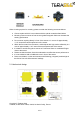
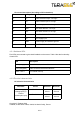

Pin out and description (According to DF13 datasheet)
Pin
Designator
Description
1
Tx
UART transmit output. 3.3V logic
2
Rx
UART receive input. 3.3V logic
3
GND
Power supply and interface ground
4
SDA
I2C serial data line. 3.3V logic
5
SCL
I2C serial clock line. 3.3V logic
6
rfu
RESERVED FOR FUTURE USE
7
5V
+5V supply input
8
GND
Power supply and interface ground
9
rfu
RESERVED FOR FUTURE USE
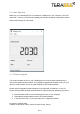
4.2.1
Backboard LEDs
Five LEDs are mounted to give visual feedback on the sensor. Table 2 lists the functionality
of each LED:
LED
Description
PWR (orange)
Power indicator, on when 5V connected
Rx/Tx (red/green)
UART receive and transmit indicators
LED 0 / LED 1
For internal use only
4.2.2
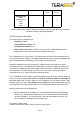
Electrical characteristics
DC electrical characteristics
Parameter
Sensor
Minimum
Maximum
Power supply
Voltage input (V)
Current
consumption (mA)
Evo 60m
4.75 V
90 mA
5.25 V
330 mA
Evo 600Hz
4.75 V
95 mA
5.25 V
190 mA
Copyright © Terabee 2018
Terabee, 90 Rue Henri Fabre, 01630, St Genis-Pouilly, France
9/14