
Data Sheet

Copyright © Terabee 2018
Table of contents:
1 Introduction 3
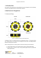
2 Mechanical Integration 3
2.1 Mechanical Design 3
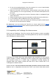
2.2 Compatibility with TeraRanger Evo distance sensors 4
2.3 Electrical characteristics 5
3 USB interface 6
3.1 Graphical User Interface 6
3.1.1 Basic Operation 6
3.1.2 Firmware Upgrade 8
3.2 Connecting the TeraRanger Tower Evo to a Host Computer 8
3.2.1 Prerequisites 9
3.2.2 Terminal Emulation Software (H-Term) 9
3.3 LEDs 10
4 UART interface 11
4.1 Pinout information 11
4.2 UART protocol information 13
4.3 Interface for visual signalization 14
5 Communication and Modes 15
5.1 Enable / Disable Tower Evo communication 17
5.2 Printout modes 17
5.2.1 Commands 17
5.2.2 Output format 18
5.3 Operating modes 19
5.3.1 Commands 20
5.4 Output-rate modes 20
5.4.1 Commands 21
5.5 Visual signalization 21
5.6 Internal Measurement Unit (IMU) options 21
5.6.1 Euler mode 22
5.6.2 Quaternion mode 23
5.6.3 Quaternions and linear acceleration 23
5.6.4 Commands 23
5.6.5 Output format 24
5.7 Command validation 26
Terabee Website:
90 Rue Henri Fabre Technical support:
01630, Saint-Genis-Pouilly Commercial:
www.teraranger.com
support@teraranger.com
teraranger@terabee.com
2/27