Copyright © Terabee 2018 User Manual for TeraRanger Tower Evo Hardware revision 1.0 Firmware revision 1.1.1 Terabee Website: 90 Rue Henri Fabre Technical support: 01630, Saint-Genis-Pouilly Commercial: www.teraranger.com support@teraranger.com teraranger@terabee.
Copyright © Terabee 2018 Table of contents: 1 Introduction 3 2 Mechanical Integration 3 2.1 Mechanical Design 3 2.2 Compatibility with TeraRanger Evo distance sensors 4 2.3 Electrical characteristics 5 3 USB interface 6 3.1 Graphical User Interface 6 3.1.1 Basic Operation 6 3.1.2 Firmware Upgrade 8 3.2.1 Prerequisites 9 3.2 Connecting the TeraRanger Tower Evo to a Host Computer 3.2.2 Terminal Emulation Software (H-Term) 3.3 LEDs 8 9 10 4 UART interface 11 4.
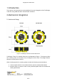
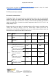
Copyright © Terabee 2018 1 Introduction The purpose of this document is to give guidelines for use and integration of the TeraRanger Tower Evo using USB and UART communication interfaces. 2 Mechanical Integration 2.1 Mechanical Design Figure 1. TeraRanger Tower Evo external dimensions TeraRanger Tower Evo external dimensions are illustrated in Figure 1. The frame provides four mounting holes on the bottom side, all designed for M3 screws. The straight distance between mounting holes is 49.8mm.
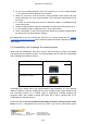
Copyright © Terabee 2018 ● ● ● ● ● ● Do not mount anything directly in front of the sensors or in a cone of approximately +/-15° around the central optical axis of the sensor Within the first meter from the sensors, during operation avoid objects with high surface reflectivity in a cone of approximately +/-45° around the central optical axis of the sensor It is better to avoid having other sources of Continuous Wave or modulated IR light close to the sensor Please consider that dust, dirt and condensatio
Copyright © Terabee 2018 arrays, please purchase the TeraRanger Hub Evo board separately, along with suitable TeraRanger Evo distance sensors. 2.3 Electrical characteristics DC electrical characteristics TeraRanger Tower Evo is powered by an external power source, and can not be directly powered by USB. The following table describes the current and voltage requirements to make the TeraRanger Tower Evo work correctly.
Copyright © Terabee 2018 **Maximum current consumption with eight TeraRanger Evo sensors connected and looking at long-range/low reflectivity targets or infinity in simultaneous mode. Drops significantly in sequential mode and varies with target reflectivity and distance. * Standby values (The sensor is not actively emitting light). Stresses above the absolute maximum ratings may cause permanent damage to the device.
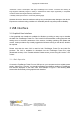
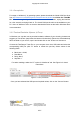
Copyright © Terabee 2018 Figure 2. Graphical user interface # Display Description 1 Measurement Provides 4 or 8 distance values in millimeters. Sensors are numbered as per the Hub Evo board. Example: TR Evo 4 will stream distance data connected to connector Nr 4 on Hub Evo. In case “-1” value is received, no sensor is connected or not able to measure. In case “+Inf” is received, the measurement is out of range. In case “-Inf” is received, the measurement is below minimum range.
Copyright © Terabee 2018 100Hz, F 250Hz, F 500Hz, F 600Hz or ASAP (As Soon As Possible). 6 IMU Enable or disable the option for Inertial Measurement Unit readings. Three IMU modes are available for preview: Euler mode, Quaternion mode, Quaternion and Linear Acceleration mode. 7 LED thresholds Adjust between three levels of visual signalization provided to discriminate three different ranges. These values can span from 0.5m to 8m with a granularity of 0.1m. Please see section 4.3 for details. 3.1.
Copyright © Terabee 2018 3.2.1 Prerequisites For usage on Windows (7, 8) operating system, please download the Virtual COM Port driver from http://www.st.com/en/development-tools/stsw-stm32102.html and follow the ”ReadMe file” instructions given by the installer. After successful installation, unplug the interface for a few seconds, and plug it back in. The virtual COM port should now be available on your PC.
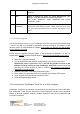
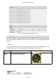
Copyright © Terabee 2018 Figure 4. Distance data stream using H-Term To communicate with the distance sensors connected to Tower Evo via the terminal emulation software, you need to send a command in hexadecimal via the “Type” box. For this, select the “HEX” Type as illustrated in the figure above. Figure 4 shows an example of the command which allows data to be shown in TEXT mode. All commands are detailed in section 5. 3.
Copyright © Terabee 2018 LED 0 (blue) One blink for each TeraRanger Evo sensor detected by the Hub Evo. Example: if 8 sensors are connected, the blue LED will blink 8 times before sending distance data. LED 1 (green) Continuous blinking indicates that distance values are being sent. The blink rates will be slower or faster, depending on the output rate selected. See section 5.4 for details. LED 2 (red) Continuous blinking indicates an error. 4 UART interface 4.
Copyright © Terabee 2018 Figure 5. UART for Hub Evo board The UART for Hub Evo board uses a single 6 pin Hirose DF13 connector for interfacing to the host system. The mating connector is a Hirose DF13-6S-1.25C with crimping contacts DF13-2630SCF (tin) or DF13-2630SCFA (gold).
Copyright © Terabee 2018 Figure 6. Pinout layout for UART 4.2 UART protocol information The UART communication for the TeraRanger Tower Evo uses a simple Modbus-like protocol. The communication parameters are: Baud Rate: 921600 baud Data Bits: 8 Stop Bit(s): 1 Parity: None HW Flow Control: None Terabee Website: 90 Rue Henri Fabre Technical support: 01630, Saint-Genis-Pouilly Commercial: www.teraranger.com support@teraranger.com teraranger@terabee.
Copyright © Terabee 2018 4.3 Interface for visual signalization Tower Evo provides an interface to control an intelligent LED light source compatible with WS2812B serial communication protocol. It allows you to drive up to four RGB LEDs through a single wire provided that the LEDs sink current is kept within the power budget indicated in the manual (ref. Section 2.3).
Copyright © Terabee 2018 Connector type and name: Pin Designator Description 1 5V +5V supply output 2 RFU Do not connect, reserved for future use 3 DOUT Control data output to drive four WS2812B Leds 4 GND Power supply and interface ground Figure 7. WS2812B serial communication, pinout layout 5 Communication and Modes The current Tower Evo firmware (1.1.1) provides four parameters for optimization of Tower Evo performance. The following parameters can be configured: 1. 2. 3. 4.
Copyright © Terabee 2018 Figure 8. TeraRanger Tower Evo modes For each command sent, a response is generated to inform the user whether the command has been validated. Command responses consist of four bytes and is a hexadecimal value. Please note that it is crucial to receive an answer to a command, before communicating the next one. For more information on response values, please reference section 5.6. Terabee Website: 90 Rue Henri Fabre Technical support: 01630, Saint-Genis-Pouilly Commercial: www.
Copyright © Terabee 2018 5.1 Enable / Disable Tower Evo communication In order to enable communication with Tower Evo and send commands to modify system performance, first please make sure streaming is enabled. 5.1.1 Commands Action Type Mode name Hex Command Enable/disable communication Activate streaming 00 52 02 01 DF Deactivate streaming 00 52 02 00 D8 5.2 Printout modes The current Hub Evo firmware supports two display modes, available via terminal emulation software: (1) Text and (2) Binary.
Copyright © Terabee 2018 5.2.
Copyright © Terabee 2018 If the target is too close the TeraRanger Evo sensor (below the minimum distance), the associated distance value is replaced by the hexadecimal value 0x0000. If the target is too far from the TeraRanger Evo sensor (above the maximum distance), the associated distance value is replaced by the hexadecimal value 0xFFFF. 5.3 Operating modes The current Tower Evo firmware provides three operating modes: (1) Simultaneous mode, (2) Sequential mode and (3) Tower mode.
Copyright © Terabee 2018 Simultaneous mode Supports simultaneous sensor operation, enabling the highest possible sampling rates. Please note that using Tower Evo with 8 distance sensors in simultaneous mode can result in sensor crosstalk. When using a Tower Evo with 4 sensors and a 90 degree angle between each, crosstalk is highly unlikely to occur.cross-talk. 5.3.
Copyright © Terabee 2018 5.4.1 Commands Action Type Update rate Hex Command Modify update rate ASAP (default) 00 52 03 01 CA 50 Hz 00 52 03 02 C3 100 Hz 00 52 03 03 C4 250 Hz 00 52 03 04 D1 500 Hz 00 52 03 05 D6 600 Hz 00 52 03 06 DF 5.5 Visual signalization The Tower Evo is shipped with default pre-programed thresholds, but you can set your own by using the command below: Action Type Hex Command Set visual signalization threshold 00 53 01 UU LL CRC8 The command is a six byte command.
Copyright © Terabee 2018 Magnetic fields and vibration can disrupt IMU calibration. In order to force a self-calibration of the IMU, move the TeraRanger Hub Evo in ways that use the full range of each axis. Here is a non-exhaustive list of motions that help with calibration: 1. 2. For magnetometer and gyroscope: (1) draw a figure of eight into the air, (2) make a full turn in the two directions of each axis (6 rotations in total).
Copyright © Terabee 2018 Please note that 0° for pitch and roll angle means that the TeraRanger Tower Evo is horizontal. 5.6.2 Quaternion mode To deal with matrix rotation in space, the quaternion approach simplifies the heavy math related to trigonometry and reduces the processing power requirements and optimizes the speed of operations. The Hub Evo can provide this kind of information through internal pre-processing and data fusion.
Copyright © Terabee 2018 5.6.5 Output format Printout mode IMU mode Description Binary Quaternion Data output (12 bytes message): IM 0x01 WW XX YY ZZ CRC8 - - Euler Header (two characters): I (73 decimal / 0x49 hex) and M (77 decimal / 0x4D hex) Mode (1 byte) This byte indicate in which IMU mode you are. For quaternion this byte is equal to 0x01 Orientation data in quaternion format (2 bytes per coordinate), each two bytes represent a signed 16 bit value.
Copyright © Terabee 2018 - - - Orientation data in quaternion format (2 bytes per coordinate), each two bytes represent a signed 16 bit value. You need to divide those four values by 2^14. Linear acceleration (2 bytes per axis), each two bytes represent a signed 16 bit value. Those value are expressed in mg.
Copyright © Terabee 2018 Quaternion and Linear acceleration Data output: IM\t www\txxx\tyyy\tzzz\txxx\tyyy\tzzz\r\n - Header (two characters): I (73 decimal / 0x49 hex) and M (77 decimal / 0x4D hex) Tabulation: \t (9 decimal / 0x09 hex) Orientation data in quaternion format.You need to divide those four values by 2^14. Linear acceleration. Those value are expressed in mg. Carriage return character: \r (13 decimal / 0x0D hex) New line character: \n (10 decimal / 0x0A hex) 5.
Copyright © Terabee 2018 Action Type Valid responses Enable/disable communication 30 05 00 A0 Modify printout mode 30 01 00 F4 Modify operating modes 30 03 00 DE Modify update rate 30 05 00 A0 Modify IMU mode 30 04 00 B5 Modify LED threshold 30 05 00 A0 Terabee Website: 90 Rue Henri Fabre Technical support: 01630, Saint-Genis-Pouilly Commercial: www.teraranger.com support@teraranger.com teraranger@terabee.