INSTALLER / CONSUMER SAFETY INFORMATION PLEASE READ THIS MANUAL BEFORE INSTALLING AND USING APPLIANCE WARNING! IF THE INFORMATION IN THIS MANUAL IS NOT FOLLOWED EXACTLY, A FIRE OR EXPLOSION MAY RESULT CAUSING PROPERTY DAMAGE, PERSONAL INJURY OR LOSS OF LIFE. Direct Vent Zero Clearance Gas Fireplace Heater Models: DV1000N/P, DV1200N/P, DV1400N/P FOR YOUR SAFETY Installation and service must be performed by a qualified installer, service agency or the gas supplier.
Temco DV1000/1200/1400 Series Table of Contents PLEASE READ THE INSTALLATION & OPERATING INSTRUCTIONS BEFORE USING APPLIANCE. Thank you and congratulations on your purchase of a Temco Fireplace Products fireplace. While we have written these instructions as accurately and thoroughly as possible, they may not cover every system, variation or contingency. Also, questions of interpretation may arise.
Temco DV1000/1200/1400 Series Installation & Operating Instructions This gas appliance should be installed by a qualified installer in accordance with local building codes and with current CSA-B149.1 Installation codes for Gas Burning Appliances and Equipment. For U.S.A Installations follow local codes and/or the current National Fuel Gas Code. ANSI Z223.1/NFPA 54. FOR SAFE INSTALLATION AND OPERATION PLEASE NOTE THE FOLLOWING: 1 .
Temco DV1000/1200/1400 Series Installation & Operating Instructions Requirements for the Commonwealth of Massachusetts All gas fitting and installation of this heater shall only be done by a licensed gas fitter or licensed plumber.
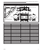
Temco DV1000/1200/1400 Series Fireplace Dimensions 4" (102 mm) Dia. 7" (178 mm) Dia. Rough Opening Depth Q T C L J Bottom Gas Line Access I O 3 m m ) S - Rough Opening Width (1 Rough Opening Height P 1/ 2" Q Gas Line Access NOTE: Flex pipe dimaeters are 4” for inner pipe and 7” for outer pipe. B J Box Access N D R C F K H M L E G J Box Access Gas Line Access N K L M A Fig. 1 Fireplace specifications and framing dimensions. Ref.
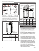
Temco DV1000/1200/1400 Series Firestop/Wall Sleeve Locating Your Fireplace VEF (Vinyl Siding) or BEF (Brick) Extension flange Combustible Construction Allowed Y A E D X 10³⁄₄" (273mm) Min. Standoff X C Y Vent Terminal B D B C F B LU584-1 LU584-T Locating unit C) As an 12/18/02 djt Fig. 2 Locate gas fireplace.
Temco DV1000/1200/1400 Series 5. Drywall can be extended flush on the bottom, top and to the outermost part of the sides of the fireplace. 6. Noncombustible materials such as brick and tile can be extended across the face of the fireplace. If brass trim kit is going to be installed, brick and tile will have to be installed flush with the front of this appliance. V W X Y Z A B C D E Clearance to Combustibles Top of unit to ceiling* ................................
Temco DV1000/1200/1400 Series tighten the flexible tube at the shut off valve and at the gas control. 3. When using a flex connector,* use only approved fittings. When a union is installed, provide easy access in it’s placement for servicing. Refer to gas specification for pressure details and ratings. 4. When a vertical section of gas pipe is required for the installation, a condensation trap is needed. In Canada see CSA - B149.1 for code details. See the National Fuel Gas Code ANSI Z223.1/NFPA 54 in the USA.
Temco DV1000/1200/1400 Series General Venting When locating the vent termination, the minimum vent clearances must be observed. (Page 10, Fig. 9) NOTE: Local codes may require different clearances. It is recommended that the termination not be located within 24” (305mm) of garden sheds, fences, decks, utility buildings or other obstructions. Do not locate termination cap where excessive snow or ice build up may occur.
Temco DV1000/1200/1400 Series General Venting Information - Termination Location INSIDE CORNER DETAIL V D H A V N N E L V B V F C B Fixed Closed Ope V V VENT TERMINATION B V rab Operable le B CFM145a G B V V Fixed Closed J G X B I A X AIR SUPPLY INLET M C = Clearance to permanently closed window D = Vertical clearance to ventilated soffit located above the terminal within a horizontal distance of 2 feet (610mm) from the center line of the terminal E = Clearance to unventi
Temco DV1000/1200/1400 Series Termination Clearances Termination clearances for buildings with combustible and noncombustible exteriors. Inside Corner Alcove Applications* Outside Corner G= Combustible 6" (152 mm) G F= Combustible 6" (152 mm) Noncombustible 2" (51 mm) V Noncombustible 2" (51 mm) V C V E O F Balcony with perpendicular side wall Balcony with no side wall D C E = Min. 6” (152 mm) for non-vinyl sidewalls Min. 12” (305 mm) for vinyl sidewalls O = 8’ (2.4 m) Min. M M No.
Temco DV1000/1200/1400 Series Vent Opening for Combustible Wall 9³⁄₄” (248 mm) MIL 5⁷⁄₈” (149 mm) 10³⁄₄” (273 mm) L-P AC 4⁷⁄₈” (124 mm) AC L-P MIL Framing Detail Fireplace Hearth Opening for Noncombustible Wall NOTE: Apply sealant “Mill-Pac” to inner pipe and “Mill-Pac” or high temperature silicone sealant to outer pipe. Sealant should be applied at every joint in the vent system including at the fireplace and T182 at the vent terminal. T182 Rnd. 8” Dia. (203 mm) Min. sealant Fig.
Temco DV1000/1200/1400 Series • Lengths of co-axial flex may be joined together using a flex connector kit (GFPVCK) only, maximum 1 kit per installation. An extension collar is included with side wall cap kits to simplify the connection of the flex pipe to the fireplace. Refer to Page 14, Figure 22. ATTENTION: Spacer springs must be installed when installing flexible venting systems. Wrap spacer spring around flex flue pipe and overlap spring ends approximately 2” (610 mm).
Temco DV1000/1200/1400 Series No more than (4) 90° and (2) 45° offsets are to be used per installation. Vent terminal cap location should be in accordance with the Venting Graph chart and the Vertical Termination Location information. 9¹⁄₂ " (24 1m m) 1. Measure the total wall thickness. Determine whether or not the thimble extension is needed. If the combustible wall depth is over 5” (127 mm), the extension should be used. (Fig. 19) 2. Assemble wall thimble with thimble extension flange to top.
Temco DV1000/1200/1400 Series 8. To finish connections, place a small bead of silicone to the outside of the fireplace inlet flange. Then, slide the extension collar over the inlet flange and secure with the three (3) screws provided. NOTE: We recommend driving in two (2) sheet metal screws at 180° adjacent to the gear clamp at each joint. Roof 6' (1.8m) Maximum Flex Vent Through the Roof (Vertical) Applications All models are approved for: 1. Vertical venting up to 35’ (10.7 m) with 7” x 4” flex. 2.
Temco DV1000/1200/1400 Series tion and building materials. An attic insulation shield (AS7-8) may be used above the firestop to keep attic insulation spaced away from the vent system. 8. Rigid pipe section included with vertical termination must be used in conjunction with the roof support so that the termination is secure in winds. All vent kit components can be assembled on the ground first, then lift complete assembly onto the roof and feed flex vent down thru the roof opening and firestop thimble assembly.
Temco DV1000/1200/1400 Series blockage of venting system. When using snow blowers, make sure snow is not directed towards vent termination area. The TDV series is considered a “special vent system”. Check with local codes or in the absence of same, with CSA B149.1 installation codes regarding special vent termination clearances. NOTICE: Flexible and rigid vent system components are not interchangable unless otherwise specified in the venting instructions.
Temco DV1000/1200/1400 Series 5. Align the flue and inlet pipes of each vent section to the mating component, then slide the sections together. Before a joint in the system is secured, push the vent components together using moderate force to ensure joint overlap of approximately 1¹⁄₂” (38 mm). 6. Secure vent components with a minimum of three (3) screws at each joint (pipe joint to pipe, joint sealants are not required). Never use screws in vent systems longer than 1” (25 mm). 7.
Temco DV1000/1200/1400 Series Corner Installation Horizontal Vent Up & Out Vent Horizontal 10" (254mm) Min. HSQ47 HSQ47 TDV90 C A Min. TDV45 F E D TDV90 L (Ref.) TDV45 B Min. M* Min. N Max. Horzontal Vent Vertical Vent Cap telescopes may be cut off to achieve minimum framing depth 16¹⁄₃₂" (407mm) TDV45 HSQ47 10" (254mm) Min. 1/2" (13mm) K* L J P Min. G* Min. H *NOTE: Refer to Offset Chart on Page 17 for Maximum Horizontal Runs O Max. T198 Fig.
Temco DV1000/1200/1400 Series Simpson Dura-Vent Venting Horizontal or Vertical Terminations The Simpson Dura-Vent Direct Vent System (GS 4” x 6⁵⁄₈”) offers a complete line of component parts for installation of both horizontal and vertical installations. Many items are offered in decorative black, as well as galvanized finish. The galvanized finish may be used for installation with your Temco gas fireplace.
Temco DV1000/1200/1400 Series Flexible Venting Individual System Components A Vent Kit GFP74FV3 GFP74FV10 GFP74FV20 GFP74FV30 A 3’ (914 mm) 10’ (3 m) 20’ (6 m) 30’ (9 m) HFTK Horizontal Flex Terminal Kit (76478) RF7612 Roof Flashing (6/12 to 12/12) (Used with 7” dia. pipe system only) (76049) AS7-8 Attic Insulation Shield (76093) HTG Horizontal Terminal Guard Kit (75783) SC7 Storm Collar (Used with 7” dia. pipe system only) (760505) RF705 Roof Flashing (0/12 to 5/12) (Used with 7” dia.
Temco DV1000/1200/1400 Series Vertical Termination Cap Storm Collar Vent Guard HTG Vertical Termination Kit Horizontal Termination Cap (Part #984) Adjustable Flashing 0/12 to 6/12 Vinyl Siding Standoff (Part #950) (Optional) Wall Penetration Heat Shield (Wall thimble) (Part #942) Pipe Length (Refer to Parts List) Elbow Alternate Snorkel Termination Cap Part #982 (14”) Part #981 (36”) Pipe Length (if required) All Simpson Dura-Vent components are available from your Dura-Vent Distributor Horizontal
Temco DV1000/1200/1400 Series Secure Vent Venting Components Standard Horizontal Kit Includes: 90° Swivel Black Elbow Decorative Black Plate Horizontal Termination Cap Horizontal Kit Includes: 90° Swivel Black Elbow Decorative black Plate Horizontal Termination Cap Adjustable Length 12” Black Length 24” Horizontal Kit Includes: 90° Swivel Black Elbow Decorative black Plate Horizontal Termination Cap Adjustable Length 12” Black Length 24” Wall Radiation Shield Vertical Flat Roof Kit Flat Roof Flashing Storm
Temco DV1000/1200/1400 Series Operating Instructions WARNING: Do not operate appliance with the glass front removed, cracked or broken. • The use of substitute glass will void all product warranties. • Care must be taken to avoid breakage of the glass. • Do not operate this fireplace without the glass front or with a broken glass front. • Replacement of the glass should be done by a licensed or qualified service person. • Do not remove the glass door when unit is hot to the touch.
Temco DV1000/1200/1400 Series After completing Steps 1 and 2, the louvre assembly should look like the illustration shown in Figure 31. Models DV1000, DV1200 and DV1400: To install the bottom louvre assembly, hook the top louvre blade ends over the top hang tabs located at the left and right ends of the panel opening. 9. Replace glass door. The door must be installed before operating the fireplace. (Refer to Page 24) 10. Flame should not impinge (touch) on logs.
Temco DV1000/1200/1400 Series Speed Control Switch 1. The blower combination on/off switch and electronic speed control is supplied loose to allow mounting in a conveniently located wall mounted electrical box. 2. Wire speed control into black (hot) side of 120V, 60Hz line as shown in blower wiring diagram. Temperature Sensor Speed Control Switch Black 120 Volt TL121 Fig. 34 DV1000 and DV1200 logs in final position. Fan White G Green T173 Fig. 36 Fan wiring diagram.
Temco DV1000/1200/1400 Series Fan Operation Wall Switch (not supplied) Thermopile Pilot Ignitor Pilot Screw OT PIL TH HI OF F P I LOT ON OF F OFF IN TP LO Flame Characteristics THTP E A OUT Manifold Pressure Supply Pressure It is important to periodically perform a visual check of the pilot and burner flames. Compare them to Figure 39. To Piezo Thermocouple FP387 Fig. 37 Pilot and valve wiring.
Temco DV1000/1200/1400 Series Lighting And Operating Instructions FOR YOUR SAFETY READ BEFORE LIGHTING WARNING: If you do not follow these instructions exactly, a fire or explosion may result causing property damage, personal injury or loss of life. A. This appliance has a pilot which must be lit manually. When lighting the pilot follow these instructions exactly. B. BEFORE LIGHTING smell all around the heater area for gas.
Temco DV1000/1200/1400 Series Troubleshooting SIT Millivolt Valve NOTE: Before troubleshooting the gas control system, be sure external shut off is in the “ON” position. WARNING: Before doing any gas control service work, remove glass front! Table 1 Valve Type NOVA MV Plus Main Operator Minimum Voltage 145mV Coil Resistance 2.25Ω ± 0.5Ω Safety Magnet Hold-in Current Less than 285mA Drop-out Current Greater than 125mA Coil Resistance 0.108Ω ± 0.003Ω System Checks Problem Pilot will not light.
Temco DV1000/1200/1400 Series System Checks (continued) Problem Possible Cause Solution Defective thermocouple. (mv Plus systems) Verify that thermocouple is not kinked or damaged. Check open circuit voltage of thermocouple. Voltage should be between 18mv and 28mv. If voltage is less than 14mv, replace thermocouple. After the pilot has been lit for approximately three minutes, and only the thermo-generator wire connected to the main operator head, measure the voltage across TPTH and TP.
Temco DV1000/1200/1400 Series System Checks (continued) Problem Possible Cause Thermo-generator output voltage not within design parameters. Defective thermostat or thermostat wiring Thermostat/wall switch will not cycle mian burner. Defective wall switch. Excessive wire resistance. Valve wired wrong. Main burner lights in the PILOT position. Main operator coil defective. Debris on seat of main valve.
Temco DV1000/1200/1400 Series Maintenance Once installed, the unit should be operated at least three (3) times to ensure that all is in working order. NOTE: Manufacturing oils will smoke during initial firing of appliance. Open windows for ventilation. Unit Adjustment Before leaving, the installer should make the following checks: Btu Input/Gas Pressure The fireplace input is marked on the Rating Plate.
Temco DV1000/1200/1400 Series Cleaning This unit should be cleaned and serviced by a Qualified Gas Technician at least annually. More frequent cleaning may be necessary if pet hair accumulates, dust and lint are present, or if the unit is located in a high traffic area. A Qualified Agency is defined in the Gas Code. Cleaning should include burner tubes, orifice/injectors (refer to section B.3 National Fuel Gas Code), logs, ceramic base, and pilot assembly.
Temco DV1000/1200/1400 Series Model DV1000N DV1000P DV1200N DV1200P DV1400N DV1400P Model DV1000N DV1000P DV1200N DV1200P DV1400N DV1400P Normal and High Direct Vent Units - Inputs - Orifice Size - Altitude BTU/Hr BTU/Hr Manifold Pressure Orifice 0 - 2000ft. Altitude in USA Min. Input Max. Input @ Max. Orifice 0-4500ft Altitude in Canada 12,500 18,500 3.5”w.c. #46 DMS 12,500 18,500 10.0” w.c. #56 DMS 13,000 20,000 3.5” w.c. #45 DMS 13,000 20,000 10.0” w.c. #55 DMS 15,000 22,000 3.5” w.c.
Temco DV1000/1200/1400 Series DV1000 / DV1200 / DV1400 Replacement Parts Ref. 1. 2. 3. 4. 5. 6. 6a. 6b. 6c. 6d. 6e. 7a. 7b. 8. 9. 10a. 10b. 11a. 11b. 12. 13. 14. 15. 16. 17. 18. 19. Description Burner Gasket Tape 5/8” Wide Gas Valve LP (SIT) Gas Valve NG (SIT) Glass Door Assembly Log Set Log, Front Log, Back Log, Right Twig Log, Left Twig Log, Twig (Top) LP/Propane Burner Orifice Natural Gas Burner Orifice Piezo Ignitor Pilot, Natural (SIT) Pilot, Orifice, Natural Pilot, Orifice, LP Rep. Reg.
Temco DV1000/1200/1400 Series Limited Warranty TEMCO Fireplace Products Direct Vent Gas Fireplaces This warranty is limited to TEMCO Fireplace Products Direct Vent Gas Fireplaces (henceforth, Product) manufactured by CFM Specialty Home Products (henceforth, CFM). ONE YEAR WARRANTY CFM warrants all components of the Product to be free of defects in materials and workmanship for a period of one year from the date of installation, with the exception of the warranty on logs and ember base.
Temco DV1000/1200/1400 Series TEMCO FIREPLACE PRODUCTS DIRECT VENT FIREPLACES INSTALLATION AND STARTUP CHECKLIST Customer Copy NOTE: TEMCO Fireplace Products gas logs and fireplaces require installation by a qualified gas appliance installer. A copy of this checklist must be submitted, along with proof of purchase, when applying to Technical Services for prior written approval of warranty repair or replacement. ❑ Read and understand installation instructions before attempting installation.
Temco DV1000/1200/1400 Series TEMCO FIREPLACE PRODUCTS DIRECT VENT FIREPLACES INSTALLATION AND STARTUP CHECKLIST Installer’s Copy NOTE: TEMCO Fireplace Products gas logs and fireplaces require installation by a qualified gas appliance installer. A copy of this checklist must be submitted, along with proof of purchase, when applying to Technical Services for prior written approval of warranty repair or replacement. ❑ Read and understand installation instructions before installing.
Temco DV1000/1200/1400 Series Customer Copy Model # ______________________________________ Serial # ______________________________________ I certify that I have followed all codes and regulations and adhered to the TEMCO Fireplace Products installation instructions. I have completed the proper installation and startup checklist. Installer’s Signature Print Installer’s Name Purchaser _____________________________________ WARRANTY REGISTRATION Please answer the following questions (Check Box): 1.
CFM Corporation 2695 Meadowvale Blvd. • Mississauga, Ontario, Canada L5N 8A3 800-668-5323 • www.cfmcorp.