Phonecell® SX5T CDMA2000® 1X Fixed Wireless Terminal 800/1900 MHZ CDMA USER MANUAL 4/19/04 Part Number 56029901
QUICK CONNECTION GUIDE SX5 Fixed Wireless Terminal Phonecell® SX5T CDMA ii User Manual
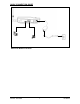
CONTENTS Phonecell® SX5T CDMA FWT Spike Antenna Power Supply AC Power Cord Before installing the Phonecell® SX5T, carefully remove the contents from the shipping carton and check for evidence of shipping damage. If damage is found, contact your Authorized Telular Distributor or shipping agent immediately. SAFE OPERATION INSTRUCTIONS IMPORTANT! Before installing or operating this product, read the SAFETY INFORMATION section of this manual. • Install the unit indoors.
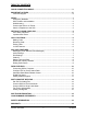
TABLE OF CONTENTS QUICK CONNECTION GUIDE ......................................................................................ii IMPORTANT NOTICES.................................................................................................iii Technical Support ......................................................................................................iii SETUP............................................................................................................................
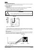
SETUP Safe Operation Requirement The Phonecell® SX5 must be either wall mounted or desk mounted and should not be operated when any person is within 203 mm (8 inches) of the antenna. Emergency Batteries Install Batteries 1. Remove the battery access door screw located on the bottom of the unit - see Figure 3. 2. Press the battery access door tabs and remove the battery access door. 3. Install 4 “AA” alkaline batteries (not supplied) - see Figure 3. 4. Reinstall the battery access door using the screw.
SX5 Location and Installation The SX5 comes with a standard spike antenna (TNC) - see Figure 5. For optimal signal strength, choose a location that is above ground and as close to windows (or exterior walls) as possible - see Figure 6. Cellular signal strength is displayed by the Received Signal Strength Indicator (RSSI) LED on the unit - See the How to Use the LED Status Indicators section of this manual. 1. Connect the antenna to the terminal - see Figure 5. 2. Finger-tighten the antenna.
Connect the SX5 to AC Power 1. A protective earth (safety ground) terminal (screw) marked with a protective earth symbol is provided on the back of the SX5 see Figure 9a. Connect this terminal to a good earth ground (i.e., a cold water pipe) by means of an 18 gauge or heavier insulated wire. The wire insulation should be green with a yellow stripe to indicate that this is a protective earth (safety ground) connection.
GETTING TO KNOW YOUR SX5 LED Status Indicators The LED indicators are activated when the SX5 is powered on. The following tables describe the modes and operation of the indicators. NOTE: If you are getting no service, contact your service provider for more information.
Hook Indicator LED Color Activity Description Green Flashing (with ringer) Incoming call Green Continuous FWT is off hook Green Fast Flashing Processing data call Green Slow Flashing Call on hold LED Color Activity Description Green Slow Flashing New voice mail or text message LED Color Activity Description Green Continuous AC power applied Amber Continuous Battery level good (battery switch on) Amber/Green Alternating Battery level poor (battery switch on) Message Indicator
CALL FUNCTIONS Making Calls 1. Pick up the telephone handset (the phone is now “off-hook”). 2. Listen for dial tone. If service is not available, a No-Service tone is produced. Hang-up the phone and try again. If the No-Service tone continues, contact your service provider to verify that cellular service is available. 3. Dial the phone number. The call will be sent automatically. HINT: Pressing the Flash key or pressing and releasing the switch-hook after dialing a number will send the call immediately.
SX5 USER FEATURES The SX5 has many user features and setup options that can be accessed using a telephone connected to the SX5. To access these features, press the key sequence for the option at any time. Some options are not available during a call. See the In-Call Functions heading in the Call Functions section for functions that are allowed during calls. All user options are activated with a sequence of digits entered from the telephone keypad.
Pulse Dial Option Press: # 12 * * # 0 = disable Pulse Dialing capability (default) 1 = enable Pulse Dialing capability Auto Dial The SX5 will recognize frequently called phone numbers and send them without waiting for the Dial Delay. Up to 50 numbers that have been successfully called at least twice will be stored when this feature is enabled. Any loss of power to the SX5 will clear this list.
Dialing Prefix Setup The SX5 allows for a prefix to be setup that will be added to the dial string of every outbound call. A maximum of 10 digits can be added to the dial string. Enable/Disable Dialing Prefix To enable press: # * 119 * 1 # To disable press: # * 119 * 0 # Configure Dialing Prefix The dial prefix can be up to 10 digits of 0 - 9, #, or *.
DATA FEATURES When connected to a personal computer (PC), the SX5 is capable of sending and receiving digital fax and data, sending and receiving email communications, and accessing the Internet. Data speeds may vary depending upon your cellular network.
View current configuration AT&V Change the port speed on the SX5T to AT+IPR= Permanently change the SX5T port speed to AT+IPR=&W Digital Fax Setup The SX5T is capable of receiving and sending faxes via a personal computer using a serial or USB port. The PC application and modem setup must be able to support software flow control.
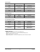
Modulation The analog modem interface can be configured to specific modulations or set to automatic modulation adjustment. NOTE: This modulation is only for the connection between the modem and the SX5. 114 # Press: # * * Supported Modulations Modulation Baud Rates (bps) V.8 Auto 0 (default) V.32bis TCM 14,400 1 V.32bis TCM 12,000 2 V.32bis TCM 9600 3 V.32 9600 4 V.32bis TCM 7200 5 V.32 4800 6 V.22bis 2400 7 V22.bis 1200 8 V.22 1200 9 V.
Air Interface Data Rates and Error Correction The SX5T supports both transparent (no error correction) and non-transparent (error correction) data connectivity along with different air interface data rates. Check with your carrier to determine which is right for your application.
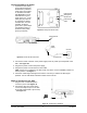
SX5T CDMA FWT WITH FAX The SX5T CDMA FWT with Fax allows connection to a fax machine and additional telephones. Simply connect your phone(s) or fax machine(s) to either or both of the RJ-11 jacks on the side of the SX5T. Figure 12 - Connecting a Phone and a Fax. Fax Timing Adjustments Phase D adjustments can be made to analog faxing. If you experience faxing issues try adjusting this setting.
SX5 TROUBLESHOOTING Telephone Service is Not Working (Cannot make or receive calls) · Make sure the SX5 powered on properly. · Make sure any equipment that is externally connected to the SX5 is connected correctly . · Test any externally connected equipment on a known system to verify its operation. · Do you have the antenna connected? If not, connect the antenna.
CONFORMANCE STATEMENTS The SX5 800/1900 MHz models are in conformance with all applicable FCC requirements. FCC Part 15/Part 22/Part 24 Class B Compliance This Phonecell® SX5 model has been tested and found to comply with the limits for a Class B digital device, pursuant to Part 15, Part 22 and Part 24 of the FCC rules. Changes or modifications not expressly approved by Telular Corporation will void your authority to operate the equipment per FCC part 15 paragraph 15.21.
Driving Check the laws and regulations on the use of cellular products in the areas where you drive. Some jurisdictions prohibit use of a cellular device while driving a vehicle. Even if your jurisdiction does not have such a law, we strongly suggest that, for safety reasons, the driver use extreme caution when operating the cellular device while the vehicle is in motion. Always obey the law. Exposure to Electronic Devices Most modern electronic equipment is shielded from RF energy.
WARRANTY I. WHAT THIS WARRANTY COVERS AND FOR HOW LONG: TELULAR CORPORATION ('Telular") warrants to a distributor Buyer, or to a customer only if the customer is a Buyer directly from Telular, that the Products (including accessories) shall comply with the applicable Specifications and shall be free from defects in material and workmanship under normal use and service for a period of fifteen (15) months from date of shipment from Telular.
IV. WHAT THIS WARRANTY DOES NOT COVER: (a) Subsequent upgrades and enhancements to the Product. (b) Defects, non-compliance or damage resulting from use of the Product in other than its normal and customary manner or environment. (c) Defects, noncompliance or damage from misuse, lightening, accident or neglect. (d) Defects, noncompliance or damage from improper testing, operation, maintenance, installation, adjustment, or any alteration or modification of any kind.
647 North Lakeview Parkway Vernon Hills, Illinois 60061, USA Tel: 847-247-9400 • Fax: 847-247-0021 E-mail: support@telular.com http://www.telular.com ©2004 Telular Corporation, all rights reserved.