
User's Manual


56019201
Pag
e
© 2000 Telular Corporation
14
objects (such as water pipes or electrical conduit or air ducts) contained within the wall directly
behind, above or below the Telguard's antenna. Never mount the Telguard on a metal surface or on
a wall that contains metal material.
When selecting a mounting location, do not mount this unit in an area where the general public could
reasonably be within 20cm (8 inches) of the antenna.
Note 1:
Optimum RF performance can usually be found at the highest point within a building with the fewest
number of walls between the Telguard’s antenna and the outside of the premises.
Note 2
: To avoid interference with other electronic devices operating in the area, avoid mounting the Telguard’s
antenna near other electronic devices. Highest radiated RF energy is in the direct horizontal line of the antenna.
Therefore vertical separation (moving electronic devices or the Telguard’s antenna either higher or lower on the
wall) provided higher levels of RF isolation from the Telguard.
Note 3
: The Telguard DataBurst unit is designed for indoor installations ONLY. Mounting the Telguard outdoors
will cause system failure and may constitute a shock hazard to humans. However, a Telguard remote antenna can
and should, whenever possible, be mounted outdoors for least RF interference.
These considerations should be coupled with the best RSSI indication obtainable (see section
5.2.8). Care should be taken to insure that a large metal object such as a refrigerator or a metal
cabinet is not located on the opposite side of the wall under consideration. Additionally, when the
system is armed, care should be taken that metal overhead doors or security gates are not moved into
a position that might cause a reduction of radio signal.
If moving the Telguard to a different location is not practical, then you may need a longer cable on
the remote antenna in order to receive adequate radio signal strength. Pick a high, visually secure
spot, using the guidelines below.
5.2.7.1 Tips for Improved Radio Signal Reception
•
The higher the antenna the better. So, start in the drop ceiling above the unit and proceed
up from there, to the roof if necessary.
•
Remember, the antenna should be as inconspicuous as possible for greatest visual security.
If on the roof, plan to place the antenna in PVC tubing or in a custom wooden structure.
•
Try to keep the antenna away from sources of RF interference, including pumps,
compressors, ovens, etc., or where metal objects can shield it or otherwise block the
cellular radio RF signal.
•
Place the antenna perpendicular to the ground, either right side up or upside down. Do not
mount the antenna horizontally.
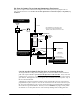
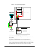
5.2.8 Measure Received Signal Strength (RSSI) for Best Antenna Placement
Measure the received signal strength by putting jumper J5 "IN". This switches the LEDs to signal
strength mode. Now, slowly move the unit or remote antenna to achieve maximum signal strength.
Pick the place where the most LEDs (up to four) are lighted. The LEDs are located on the top-right
side of the PCB and are read from bottom to top with the
Radio TX LED = 1
and the AC
Power
LED = 4
.
At least two lighted LEDs with the third LED flashing are necessary to assure
continuous, trouble free operation
. Move antenna slowly and check often. Only a few inches can
make a great difference in signal strength.
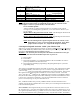
LED Function Table – View RSSI Mode
RSSI Value LED’s Lighted RF dBm
NO SVC LED 1* = on, 2-4 = off
≤
-116 dBm
0 LED 1 = on, 2-4 = off
≤
-111 dBm