
User's Manual


56019201
Pag
e
© 2000 Telular Corporation
5
NOTE
: For UL installations, all the above features
must
be enabled.
The following system trouble features are embedded in the Telguard for tripping the STC relay and
cannot be changed:
•
Trips on c
atastrophic failure
(CF) if all power is lost.
•
Trips on
transmit-disable command
from the Communication Center. This
radio command disables only the Telguard transmitter and would be used, for
example, to shut down the Telguard due to a runaway dialer. The Telguard
receiver function stays active so that a
transmit-enable command
can be
received by radio to put the Telguard back into normal service.
2.7 D
IAGNOSTIC AND
S
TATUS
LED
S
Four LEDs are provided as a useful aid during installation and give installers an immediate visual indication
of system status. These LEDs include an
AC Power LED
indicator that is green when AC power is normal
and off when AC power is low or missing. The red
STC LED
provides system trouble information for
low/missing AC power-ACFC (1 flash), low/missing battery-LBC (2 flashes), telco line fault-LFC (3
flashes), no cellular service-NSC (4 flashes), radio communication failure-RFC (5 flashes) and loss of dial-
tone voltage-DTF (6 flashes). An
Operating Mode LED
indicates solid yellow for normal operating mode
or slow flash for C/C off-hook when communicating over cellular. A short (1 second) solid green
Radio TX
LED
indicates it is in a Microburst communication cycle. Separately, these LED’s can be converted into a
bar graph during installation to indicate radio signal strength by using a single jumper (J5) to select normal
LED mode (off) or signal strength mode (on).
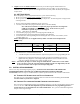
2.7.1 LED Signal Strength Indication
The Telguard provides the installer with an easy to use LED radio signal strength indicator (RSSI)
for positioning the unit or remote antenna to obtain the strongest RF signal possible. A signal
strength reading can be obtained at any time there is power applied to the Telguard without affecting
the operation of the unit. When the
“RSSI”
jumper J5 is “IN”, the Telguard displays the current
received signal strength within 5 seconds and should the jumper be inadvertently left “IN”; the
Telguard will revert to normal display operation after 10 minutes. The signal strength is read from
bottom to top using the four sequential LEDs located on the top right side of the printed circuit board
with the
Radio TX LED = 1
and the
AC POWER LED = 4
.
RSSI Value LED’s Lighted RF dBm
NO SVC LED 1* = on, LED 2-4 = off
≤
-116 dBm
0 LED 1 = on, LED 2-4 = off
≤
-111 dBm
1 LED 1 = on, LED 2 = slow flash
LED 3-4 = off
≥
-110 dBm
2 LED 1-2 = on, LED 3-4 = off
≥
-100 dBm
3 LED 1-2 = on, LED 3 = slow flash
LED 4 = off
≥
-90 dBm
(Minimum signal
strength required)
4 LED 1-3 = on, LED 4 = off
≥
-80 dBm
5 LED 1-3 = on , LED 4 = slow flash
≥
-70 dBm
6 LED 1-4 = on
≥
-60 dBm
*Note: LED 1 = Radio TX; LED 2 = Mode; LED 3 = STC; LED 4 = AC Power.
2.8 T
ELGUARD
S
ETUP
P
ROGRAMMING
P
ARAMETERS
The Telguard will not operate until the unit is activated from the Communication Center
. There are no
radio NAM programming requirements since the radios have been preprogrammed at the factory. However,
certain Telguard operating parameters may need to be changed from the factory default programming by the
installer during installation in order to have the Communication Center process alarm signals to the central
station. These are setup parameters and are used to tell the Communication Center how to encode alarm
messages to the appropriate alarm monitoring station. Included in the setup parameters are the C/C reporting
format and cellular operating system A or B. Also included are the STC supervisory trip input settings, CFC
settings, NFC/LFC trip delay time, and standby battery size. If operating parameters are not uploaded to the
Communication Center, a "missing parameters (MP) condition" exists and the Telguard will not operate.
When an MP condition exists, the Telguard causes the STC LED to light and the STC (System Trouble) trip
output to occur.