TELGUARD® Cellular Alarm Transmission System Using Microburst™ Control Channel Technology MODEL T100C001 UL R INSTALLATION AND OPERATING INSTRUCTIONS COMPANY CONFIDENTIAL For use by TELGUARD® customers only. Distribution to others strictly prohibited. T E L U L A R® CO RPO RATION Corporate Headquarters 647 North Lakeview Parkway Vernon Hills, Illinois 60061 847-247-9400 Fax: 847-247-0021 December 21, 2000 ® TELGUARD is a registered trademark of Telular Corporation.
FOREWORD Many customers purchase the Telguard because they prefer its price and features, but do not intend to use it in an application that requires UL Grade A Burglary or Fire Listings. If such UL Listings are not required, it is possible to use model T100C001 that is UL Listed for Supplemental Use only. This means that the T100C001 will not enhance the grade of service. Also, the T100C001 is not to be used as a main or secondary line for a fire or burglar alarm system.
EFFICIENT OPERATION Do not operate your Telular product when holding the antenna. Be sure to mount the unit such that its antenna is a minimum of eight (8) inches (20 centimeters) is maintained from the general public. For the best service quality, keep the antenna free from obstructions and point the antenna straight up. ANTENNA CARE AND REPLACEMENT Do not use the unit with a damaged antenna. If a damaged antenna comes into contact with the skin, a minor burn may result.
• Connect the radio/television equipment to an outlet on a branch circuit different from that to which the Telguard terminal is connected. Consult your Authorized Telular Dealer or an experienced radio/TV technician for additional suggestions. • The user or installer may find the following booklet prepared by the Federal Communications Commission helpful, “Interference Handbook”. The booklet is available from the U.S. Government Printing Office, Washington, DC 20402.
FUTURE TESTING AND LIMITATIONS ON USE Telguard is part of an advanced design alarm-communication system. It does not offer guaranteed protection against burglary and fire. Any alarm communication system is subject to compromise or failure. The Telguard will not work without power. Devices powered by AC will not work if the AC power supply is off for any reason, however briefly, and at the same time, the backup battery is missing, dead or not properly installed.
TABLE OF CONTENTS FOREWORD..................................................................................................................................................................I NOTICES........................................................................................................................................................................I ABOUT THIS MANUAL ...............................................................................................................................
4.4 CONNECT TELCO LINE AND SUPERVISORY TRIP OUTPUT..................................................................................8 4.5 COMPLETE THE INSTALLATION .........................................................................................................................8 5.0 INSTALLATION STEPS .................................................................................................................................8 STEP 1: TRANSMIT C/C ALARMS OVER THE TELCO CONNECTION ...........
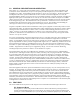
1.0 GENERAL DESCRIPTION AND OPERATION The Telguard is a cellular radio alarm transmission device, which is used to provide a backup transmission path (cellular) for control communicators (C/Cs) in case the primary transmission path (telco) is not available. When transmitting over cellular, Telguard obtains its data from the C/C by way of a telco interface.
the telco line is cut or the C/C is unable to communicate with the central station receiver due to busy telephone line circuits then Telguard transmits the alarm message over the cellular network. 2.2 C/C COMPATIBLE COMMUNICATION FORMATS The Telguard reads the C/C’s alarm messages and converts the C/C’s digital data format into Microburst packet data protocol for transmission over the cellular radio network.
2.3.4 Radio Communications Failure Condition (RFC) Radio communications failure condition (RFC) is declared when Telguard is unable to transmit over the cellular network even with acceptable signal strength. Two conditions can cause an RFC to occur, Link Request failure (RFC1) or Link Termination failure (RFC2). 2.3.4.1 RFC1 (Link Request Failure) When a LFC or CFC has been declared and there is an alarm signal to communicate, the Telguard attempts to transmit its message via radio.
2.5 TELGUARD AUTOMATIC SELF-TEST REPORT The Telguard automatic self-test signal is originated by the Communication Center on a daily, weekly, or monthly schedule. When the time for an automatic self-test occurs, the Communication Center transmits a radio signal to the Telguard and the Telguard responds with a self-test radio signal that is received by the Communication Center and processed on to the central station, just as normal alarm signals are processed.
NOTE: For UL installations, all the above features must be enabled. The following system trouble features are embedded in the Telguard for tripping the STC relay and cannot be changed: • Trips on catastrophic failure (CF) if all power is lost. • Trips on transmit-disable command from the Communication Center. This radio command disables only the Telguard transmitter and would be used, for example, to shut down the Telguard due to a runaway dialer.
If default programming is correct or operating parameters are re-programmed into the Telguard, the installer calls the Telular IVR and follows the activation procedure to request an activation "ping". The Communication Center responds with a radio acknowledgement to the Telguard clearing the STC condition and allowing the Telguard to operate over the cellular radio network. The programmed parameters are transmitted automatically to the TCC when the Telguard is activated.
2. Computer access via Telular's Intranet: Dealers may access their Telguard customer database via Telular's Intranet. The pertinent customer account information and serial number can be completed and submitted on-line. After an approval acknowledgement is issued, usually within 10-minutes, the Telguard is ready to install. 3.1 GETTING READY Before attempting to connect Telguard to the host C/C, please note the following: 1. Be sure your unit has cellular service activated. (See Section 3.0) 2.
4.3 TRANSMIT C/C ALARMS OVER THE CELLULAR RADIO NETWORK Next, you will be connecting the C/C's digital dialer output to Telguard and verifying that alarm signals can be reliably sent through Telguard over cellular to the central station digital receiver. The incoming Telco line is not connected to Telguard during this step. 4.
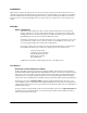
5.1 STEP 1: TRANSMIT C/C ALARMS OVER THE TELCO CONNECTION Be sure the C/C is powered up and programmed so that it will transmit a simple alarm signal over the telco line through the RJ31X to the central station when not connected to the Telguard. In checking this, do not connect the host C/C or incoming telco line to the Telguard. INCOMING TELCO RJ31X PREMISE PHONES MAKE SURE HOST C/C IS PROGRAMMED AND WORKING THROUGH RJ31X BEFORE INSTALLING TELGUARD.
5.2 STEP 2: PROGRAM TELGUARD AND CONFIRM COMMUNICATIONS INTEGRITY Confirm that Telguard's programming parameters are correctly entered into the unit, cellular service is activated, and Telguard has adequate cellular signal-strength. This is the most important step in the installation, since the programming parameters contain all the necessary information for successful communications and good signalstrength insures performance reliability. INCOMING TELCO ANTENNA RJ31X S E E AP PE NDIC ES A1 .
5.2.2 Connect Backup Battery and AC Power Transformer To apply power on model T100C001, connect the battery by attaching battery leads to terminals 3 () and 4 (+) noting polarity and program Telguard memory location 67 (see section 5.2.5) for proper battery capacity. Connect the Telguard AC power transformer to terminals 6 and 7 marked "AC 16.
5.2.4 Default Programming The Telguard default setup is pre-programmed at the factory. Default setup values are listed in Section 5.2.5 (Telguard Programming Data Sheet) and highlighted in "bold" type. Setup parameters are stored in non-volatile memory and retain their settings when power is removed from the unit. Review the default settings and record on the data sheet all changes that you make.
5.2.6 Setup & Programming When the Telguard is received from the factory and is powered up for the first time, it is immediately ready for activation after a 10-second delay, provided the default settings are what you want. The STC LED turns on steady and the STC relay is tripped. If changes to the default values are required, then the Telguard is re-programmed with a plain old telephone set (POTS) connected to J2 where the C/C is usually connected.
objects (such as water pipes or electrical conduit or air ducts) contained within the wall directly behind, above or below the Telguard's antenna. Never mount the Telguard on a metal surface or on a wall that contains metal material. When selecting a mounting location, do not mount this unit in an area where the general public could reasonably be within 20cm (8 inches) of the antenna.
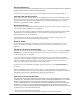
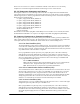
1 2 3 4 5 6 LED 1 = on, 2 = slow flash LED 3-4 = off LED 1-2 = on, LED 3-4 = off LED 1-2 =ON, 3 =SLOW FLASH LED 4 = off LED 1-3 = on, LED 4 = off LED 1-3 = on , 4 = slow flash LED 1-4 = on ≥ -110 dBm ≥ -100 dBm ≥ -90 dBm (Minimum signal strength required) ≥ -80 dBm ≥ -70 dBm ≥ -60 dBm *Note: LED 1 = Radio TX; LED 2 = Mode; LED 3 = STC; LED 4 = AC Power.
and serial number are required to enter the TEST menu if the unit has already been activated. This feature is extremely helpful when troubleshooting intermittent problems such as NSC or LFC. MOVE ON Once you have completed the Telguard Programming Data Sheet, confirmed Telguard programming, received the "activation ping" from the Communication Center and have good signal-strength, move on to Step 3.
5.3 STEP 3: TRANSMIT C/C ALARMS OVER THE CELLULAR RADIO NETWORK Confirm that the Telguard enables the host C/C to transmit alarm signals over the cellular radio network. In checking this, do not connect the incoming telco line to the Telguard or connect the supervisory trip output (STC) to the C/C zone input. INCOMING TELCO ANTENNA RJ31X S E E AP PE NDIC ES A1 .1 THRO UG H A1 .4 FOR DE TAILS O N JACK AND PI N AS SI G NM E NTS , TE RM I NAL S TRIP , JU M PE R, AN D S TATU S LED S.
5.3.2 Verify Alarm Signal Transmissions over Cellular Trip several alarms on the C/C and verify that the central station received them by calling the central station operator. Use a lineman's buttset in MONITOR MODE and connected to Telguard's "T" and "R" test pins to "listen" to communications between the C/C and Telguard.
5.4 STEP 4: CONNECT TELCO LINE AND SUPERVISORY TRIP OUTPUT Now, you are ready to connect and test the incoming telco line and the supervisory trip output to the C/C. Also, you must check to be sure that there are no other phone devices connected in front, or in parallel, of the RJ31X. B E SURE T ELGUARD IS FIR ST DEVICE ON INCOMING PHONE LINE TO PREVENT PHA NT OM TRIPPING. INCOMING TELCO ANTENNA RJ31X S E E AP PE NDIC ES A1 .1 THRO UG H A1 .
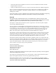
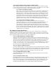
Exhibit 1. Telco Signal Path through Telguard House Phone Current Measurement Dialer Current Measurement PREMISE PHONES Telco Voltage Measurement TELGUARD T1 T R R1 T1 T R R1 J1 J2 RJ31X 6 7 5 T GREEN 4 R RED 3 2 8 R1 1 T1 BROWN GREY T1 T R R1 INCOMING TELCO Internal Circuitry Telco Dialer HOST C/C SIGPATH0.VSD 5.4.2 Connect RJ31X to Telguard Jack 1 and Check LFC Find the modular Jack-to-Jack (J/J) cable supplied and connect one end to Telguard Jack 1 and other end to the RJ31X.
5.4.4 Check Telguard Supervisory Trip to C/C After you have connected the STC trip output, check to be sure that it operates correctly. 5.4.4.1 Reprogram C/C to Send Proper Code Reprogram C/C to send proper alarm code when tripped by the Telguard’s supervisory output. Program zone restoral as desired. 5.4.4.
5.5 STEP 5: COMPLETE THE TELGUARD INSTALLATION Last step is to handle loose ends. 5.5.1 Check Settings Check the jumper setting of J5 (LED mode, out = normal). 5.5.2 Permanently Mount and Properly Ground the Telguard Chassis Attach earth ground to the green grounding screw located on lower left-hand corner of printed circuit board assembly and permanently mount the Telguard chassis.
A1.0 Wiring Diagram WARNING: HIGH VOLTAGE PRESENT ON PHONE LINES. DISCONNECT PRIOR TO SERVICING. INCOMING TELCO ANTENNA RJ31X PREMISE PHONES STATUS LEDS (See Appendix A1.4) AC POWER SYSTEM TROUBLE TELGUARD OPERATION MODE RADIO TX SIGNAL STRENGTH LEDS LED MODE SELECT J5 OUT = NORMAL IN = RSSI TRANSCEIVER T J2 R J1 * TELCO DIALER + BATTERY 12V* - BATTERY STC (N.O.) STC (COM) 1 THIS DEVICE COMPLIES W ITH FCC RULES PART 68 AND 15. FCC R EGISTR ATION NO: TBD RINGER EQUIVALENCE: 0.
A1.1 JACK AND PIN ASSIGNMENTS Jack Designation Connects To Pin Assignment Incoming Telco RJ31X Jack. 1 4 5 8 C/C Digital Dialer Digital Dialer input/output of host C/C. J4 Radio J1 Telco RJ31X. J2 Radio Interface. 56019201 Gray R1 Red R(Ring) Green T(Tip) Brown T1 Function Status LED Reference Connects telco line to Telguard and provides output for premises phone connection at RJ31X. STC LED Flash 3 times when telco voltage is lost.
A1.2 TERMINAL STRIP PIN ASSIGNMENTS Terminal Strip Pin 1 STC 2 STC Definition Supervisory Relay Trip output for programmable trouble conditions. (N.O.) Connects To 24-hour trip zone input on host C/C. Status LED Reference Function Enables transmission of programmed supervisory trouble code: When fault condition occurs: ♦ - AC Power LED OFF STC LED Flashes 1 time. AC Power Fail (ACFC). AC failure detected at 102 VAC. ♦ Low/Missing Battery Condition (LBC) due to: - Low Battery detected at 11.6 VDC.
A1.3 LED M ODES AND FUNCTIONS As shown below, J5 is a two-pin jumper used to select the LED Mode. Refer to the LED Function Tables for a description of each LED in "Normal Operating Mode" and "Received Signal Strength Mode".
A1.4 JUMPERS Jumper Feature J5 Normal Operating Mode, RSSI or Programming Mode. 56019201 Function Used as LED Mode selector to indicate operating conditions of Telguard, used to view Received Signal Strength or enter Programming Mode. Refer to A1.4. Page 27 Jumper Position In Out View Received Signal Strength or Enter Programming Mode.
A2.0 Operational Quick Reference Table Telguard Event Typical C/C Alarm Cycle over Telco Telguard System Trouble Conditions Radio Message Internal Action None None Yes AC Power off and STC flashes 1 time. Yes STC flashes 2 times. Yes STC flashes 3 times. If Selected None Monitors Telco line voltage and C/C attempts Switch to standby battery if present, monitor battery, monitor AC for restoral. If Selected None Wait for LBC restoral, charge battery. If Selected None Yes STC flashes 4 times.
A2.1 SETUP PROGRAMMING PARAMETERS Parameter Description Cellular System A or B Program Location 32 The cellular network system through which the Telguard radio is authorized to place calls to the central station. System B is the wireline system (usually operated by the local telephone company) and System A is the nonwireline system (usually operated by the telephone company's competitor). 1=A, 2=B.
A2.
A2.5 ACTIVATION FORM (FAX to 678-945-1651) Subscriber Information Telguard DataBurst Information This data is pertinent to the installation and location of the Telguard DataBurst system. The following data must be entered into the Telular Communication Center computers prior to activation on the cellular network.
A3.0 UL Installation Requirements for Supplemental Use (Model T100C001). The T100C001 is UL Listed for Supplemental Use only. This means that the T100C001 will not enhance the grade of service. Also, the T100C001 is not to be used as a main or secondary line for a fire or burglar alarm system. The T100C001 is not intended for fire remote station, proprietary and central station use.
A4.0 Detailed Specifications A4.1 DIALER TO INTERFACE ELECTRONICS The patented integrated interface by Telular, Inc. allows digital dialers to dial into the cellular radio network. • Line voltage: 48 Vdc into standard telephone device when on-hook. • Dial tone: Precision 400 Hz @-13 dBm +/- 2 dBm. 16 digits dial out capability. • Ringer equivalent: 0.0B • Mode: Loop start only. 25mA max. +/- 5% off-hook. • Protected by U.S. Patents: 4,658,096; 4,775,997; 4,922,517; 4,737,975; 4,868,519; 5,134,644. A4.
A5.0 Parts List Part No. Description Basic Hardware: Model T100C001 Economy model T100C001 is UL Listed for Supplemental Use only and is not to be used as a main or secondary line for a fire or burglar alarm system. This means that the T100C001 will not enhance nor detract from the grade of service of the UL Listed alarm system being used. Model T100C001 has a compact plastic enclosure and whip antenna.
General Accessories: BMR-1250 Battery, 12V, 7.0 AH. XXXXXTBD Transformer, 16.5V, 20VA (Revere RT-1620SL). XXXXXTBD Dipole spike antenna (0dB gain). 1F01A001 Magnetic mount antenna (3dB gain), 12 ft. cable with TNC connector. 1F01A003 Magnetic mount antenna (5dB gain), 12 ft. cable with TNC connector.
Index AC Failure Condition (ACFC)................................. 3 Aeris .......................................................................... 1 AMPS......................................................................... 1 Antenna Options ..................................................... 15 automatic self-test ...................................................... 1 Automatic Self-test Report...................................... 4 Backup batteries...............................................