Outdoor CPE8000 Installation and Configuration Guide V1.
Table of contents 1. 2. 3. OVERVIEW ................................................................................................................................................ 4 1.1. USER INTERFACE SPECIFICATION ......................................................................................................... 4 1.2. LTE INTERFACE SPECIFICATION ........................................................................................................... 4 GETTINGSTARTED ......................
PLEASE READ THESE SAFETY PRECAUTIONS! RF Energy Health Hazard The radio equipment described in this guide uses radio frequency transmitters. Although the power level is low, the concentrated energy from a directional antenna may pose a health hazard. Do not allow people to come in close proximity to the front of the antenna while the transmitter is operating.
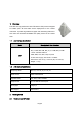
1. Overview The ODU is a high performance 4G LTE outdoor CPE product designed to enable quick LTE fixed data service deployment to the remote customers. It provides high data throughput and networking features to end users who need both bandwidth and quality service in the remote area. 1.1.
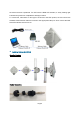
Upon receiving the product, please unpack the product package carefully. Each product is shipped with the following items: Table 2-1 Packing List Outdoor CPE Products Quantity ODU unit 1 Power adapter 1 Power Line 1 Mounting brackets 1 PC Ethernet Cable 1 If you find any of the items is missing, please contact our local distributor immediately. CPE Unit: Unpacking the Equipment Table 2-1 lists all the standard parts that are supplied in your LTE CPE Unit Installation Package.
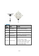
the device becomes operational. For CPE with the RUN LED indicator, a slowly flashing light indicates the system has completed the startup procedure. To connect PC, LAN switch or other type of IP device to the CPE product, the user should use standard CAT5 Ethernet cable and connect to the appropriate LAN port. Once connect the CPE LAN LED indicator should come on.
LED Display LED Function Description PWR Power Indicator Green Color – Device is powered on RUN System Run Indicator LAN LAN port status SIM SIM Card Indicator Indicator Fast Blinking – Device is rebooting Slow Blinking – Device is in normal operation Solid Green – LAN port is up Blinking Green – LAN data activity in progress Light is on – SIM card state ready.
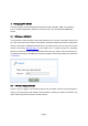
3. Managing CPE Device The ODU supports several management interfaces including TELNET, WEB, and TR-069 for local or remote managements. However normal end user is only provided with WEB based access 3.1. WEB Login--192.168.0.1 It is a preferred to setup the CPE using a Web browser from a local PC connected to device LAN port. The user should ensure that the connected PC acquired IP address via DHCP from the device.
Page 9
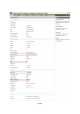
3.3. LTE Configuration Radio Settings-ND&S Configure There is a LTE radio button which is used for the user can turn the radio on or off to restart the LTE module. The CPE would scan frequency auto as soon as the system has completed the startup procedure, and you can configure the fixed Frequency manual as follow: Note: After configure any parameters of the device, you must click the “Save & Apply” button to save the configuration otherwise the configuration will not take effect.
And the CPE will obtain two different IP for two networks, as follow: Page 11
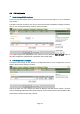
3.4. eNodeB Selection The CPE would lock on the ND&S to connecting after the operator enabled the Lock ND&S when the Co-Channel Interference (CCI) is around. PLMN Selection Setting “Network Mode” as Nomadic, then click the “Search” button, After the CPE searched the “PLMN ID”, select the applicable PLMN ID and click “Add Info list” button to add the PLMN ID to the PLMN-List.
eNodeB Setting After Enable the Preferred eNB List and configure the Earfcn/PCI, the CPE will scan the corresponding ND&S and connecting to LTE — >eNB Settings — >Enable Preferred eNB List — >Enable Lock ND&S to the preferred list—>add the Earfcn and PCI—>Save & Apply Page 13
3.5. Network Configuration Modify MTU Size The default Operation Mode is Router, and the PC of the user that connected to device LAN port will obtain IP address via DHCP server of the device.
Change model from Router to Bridge The operation mode could be changed from Router to Bridge if necessary .
data services. And the PC should configure a static IP address as 10.1.1.x manual in order to visit the CPE managing page http://10.1.1.1 . 3.6. Service Configuration-DMZ Setting By enabling this option will make the specified local LAN host (DMZ IP) was exposed to the Internet, all ports can be accessed by other computers on the Internet. 3.7. System Maintenance WEB GUI menu to configure the device in more details (see diagram below). The configuration is easy to use and self explanatory.
TR069 Configuration After setting the Device Management Mode as TR069, you must also configure the validity acs url for monitoring the device via standard TR-069 ACS systems.
Firmware Upgrade over HTTP Select the Default settings to reset the CPE after upgrade Click on the Browser button to select the firmware file to be uploaded to the device. Click the” Upgrade” button to begin the upgrade process. Please do not interrupt the upgrade process and continue to wait for the following pop window to appear. The CPE will reboot after upgrade successful.
Change Password You can select the language or modify the web login password via the Maintenance page. Load Factory Default Click the “Restore” button will restore the device to original factory setting. User will need to reconfigure the authentication setting in order to get the device operational.
4. FAQ and Troubleshooting 1) My PC cannot connect to the CPE. Re-plug the PC Ethernet cable and check if the PC LAN connection is up or showing activity. Check if the system run LED is on. If it is not, check the power cord and make sure it is connected properly. Also verify that the AC power supply is available. If the PC LAN shows no activity and system run LED is off but the power cord is connected properly and there is AC supply, then it is likely the adapter is damaged.