
User Manual

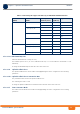
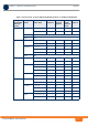
Table Of Contents
- System Manual
- BreezeCOMPACT
- About This Manual
- Contents
- Figures
- Tables
- Chapter 1 - System Description
- Chapter 2 - Commissioning
- 2.1 Introduction
- 2.2 BreezeCOMPACT Installation
- 2.3 System Initial Verification
- 2.4 Configuring Parameters Required for Management Connectivity
- 2.4.1 Configuring the BTS Number
- 2.4.2 Configuring the Management Interface Connectivity Mode Parameter
- 2.4.3 Configuring the IP Interfaces Parameters
- 2.4.4 Configuring the L1 and L2 Parameters (if necessary)
- 2.4.5 Configuring the SNMP Authorized Manager and Traps Manager
- 2.4.6 Applying the Configuration
- 2.5 Activating the Unit
- Chapter 3 - Operation and Administration

BreezeCOMPACT System Manual
Chapter 3 - Operation and AdministrationBS Menu
Chapter 3 - Operation and Administration BS Menu
70
A change in Segment Number will take effect after next reset.
3.7.2.2.2.4 Preamble Index
Read-only. The Preamble Index used by the BS (0-113).
3.7.2.2.2.5 Frame Number Offset
Controls the offset applied between the internal frame count and the reported frame number. The
available options are Zero and Random. If Random is selected, the device will choose a random number
between 0 to 15. The default is zero (0).
A change in Frame Number Offset will take effect after next reset.
3.7.2.2.2.6 Total Uplink Duration
The total duration of the uplink in a frame, in slots (one slot equals 3 symbols).
To avoid BS-BS interference, the Total Uplink Duration must be identical in all BSs in a geographical
region.
The range is 4-7 for a BS bandwidth of 5 or 10MHz, 3-5 for a BS bandwidth of 7MHz.
A change in Total Uplink Duration will take effect after next reset.
The table below provides details on DL:UL ratio as a function of BS Bandwidth and Total Uplink Duration.
3.7.2.2.2.7 Operational Status Channel 1
Read-only. The operational status of Channel 1.
3.7.2.2.2.8 Operational Status Channel 2
Read-only. The operational status of Channel 2.
3.7.2.2.2.9 Operational Status Channel 3
Read-only. The operational status of Channel 3.
3.7.2.2.2.10 Operational Status Channel 4
Read-only. The operational status of Channel 4.
3.7.2.2.3 DL Diversity Mode
The DL Diversity Mode option includes the DL Diversity Mode parameter. In the current release only
Matrix A or B is supported.
Table 3-3: DL:UL Ratios
BS Bandwidth (MHz) Total Uplink Duration (slots) DL:UL Ratio
5/10 4 35:12
5 32:15
6 29:18
7 MHz 3 24:9
4 21:12