
User Manual

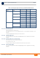
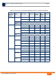
Table Of Contents
- System Manual
- BreezeCOMPACT
- About This Manual
- Contents
- Figures
- Tables
- Chapter 1 - System Description
- Chapter 2 - Commissioning
- 2.1 Introduction
- 2.2 BreezeCOMPACT Installation
- 2.3 System Initial Verification
- 2.4 Configuring Parameters Required for Management Connectivity
- 2.4.1 Configuring the BTS Number
- 2.4.2 Configuring the Management Interface Connectivity Mode Parameter
- 2.4.3 Configuring the IP Interfaces Parameters
- 2.4.4 Configuring the L1 and L2 Parameters (if necessary)
- 2.4.5 Configuring the SNMP Authorized Manager and Traps Manager
- 2.4.6 Applying the Configuration
- 2.5 Activating the Unit
- Chapter 3 - Operation and Administration

BreezeCOMPACT System Manual
Chapter 3 - Operation and AdministrationBS Menu
Chapter 3 - Operation and Administration BS Menu
68
3.7.2.2.1.3.4 Maximum Map Size
Limits the maximum size of maps (in slots).
The available options are 10, 20...300 (10xN where N=1-30) or -1 for No Limitation. The default is -1 (No
Limitation).
A change in Maximum Map Size will take effect after next reset.
3.7.2.2.1.4 Uplink Feedback Zone
The Uplink Feedback Zone menu enables viewing/updating the values configured for the following
parameter:
3.7.2.2.1.4.1 Uplink Feedback Zone Permutation Base
The permutation base used in the uplink feedback zone.
The valid range is from 0 to 69.
A change in Uplink Feedback Zone Permutation Base will take effect after next reset.
3.7.2.2.1.5 Frame Structure Mode
The Frame Structure Mode menu enables viewing/updating the values configured for the following
parameter:
Table 3-2: Calculating the Upper Limit Value (Y) for Minimum and Maximum Size
BS Bandwidth
(MHz)
Maximum Cell
Radius
Total Uplink
Duration (slots)
Extra TTG
(symbols)
Upper Limit (Y)
5/10 1, 2, 4, 8 4 0 34
6028
1, 2, 4, 8, 15, 23 5 1 30
7124
15, 23, 30 4 2 32
6226
30 5 3 28
7322
7 1, 2, 4, 8, 15, 23 4 0 20
1, 2, 4, 8, 15, 23, 30 3 1 22
5116
30 4 2 18