
User's Manual
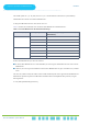
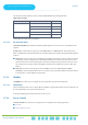
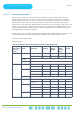
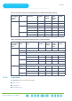
Table Of Contents
- About This Manual
- Contents
- Figures
- Tables
- Chapter 1: System Description
- Chapter 2: Commissioning
- Chapter 3: Operation and Administration

Chapter 3 - Operation and AdministrationBS Menu
Chapter 3: Operation and Administration
BS Menu
. . . . . . . . . . . . . . . . . . . . . . . . . . . . . . . . . . . . . . . . . . . . . . . . . . . . . . . .
BreezeCOMPACT System ManualBreezeCOMPACT System Manual
81
3.7.2.6 Connectivity
The Connectivity menu includes the following options:
Bearer Interface
Authentication
QOS Marking Rules
7 None 1, 2, 4, 8, 15, 23 1 0 7 24
30 3 0 7 22
Medium 1, 2, 4, 8 0 4 6 24
15, 23 2 2 6 24
30 2 4 6 22
High 1, 2, 4, 8, 15, 23 1 6 5 24
30 3 9 5 22
Table 21: Functionality of Allowed Ducting Mitigation Modes, 7 MHz BS Bandwidth
Configured
Total Uplink
Duration
(slots)
Mitigation
Mode
Maximum Cell Radius
(Km)
Extra TTG
(symbols)
Added DL
Silenced
Symbols
Actual
Uplink
Duration
(slots)
DL
Symbols
3 None 1, 2, 4, 8, 15, 23, 30 1 0 3 22
Medium N/A
High N/A
4 None 1, 2, 4, 8, 15, 23 0 0 4 20
30 2 0 4 18
Medium 1, 2, 4, 8, 15, 23 1 2 3 20
30 1 4 3 18
High N/A
5 None 1, 2, 4, 8, 15, 23, 30 1 0 5 16
Medium 1, 2, 4, 8, 15, 23 0 4 4 16
30 2 2 4 16
Long 1, 2, 4, 8, 15, 23, 30 1 6 3 16
Table 20: Functionality of Allowed Ducting Mitigation Modes, 5/10 MHz BS Bandwidth (Continued)
Configured
Total Uplink
Duration
(Slots)
Mitigation
Mode
Maximum Cell
Radius (Km)
Extra TTG
(Symbols)
Added DL
Silenced
Symbols
Actual
Uplink
Duration
(Slots)
DL
Symbols