
User's Manual
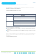
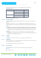
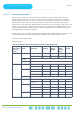
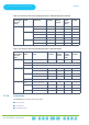
Table Of Contents
- About This Manual
- Contents
- Figures
- Tables
- Chapter 1: System Description
- Chapter 2: Commissioning
- Chapter 3: Operation and Administration

Chapter 3 - Operation and AdministrationBS Menu
Chapter 3: Operation and Administration
BS Menu
. . . . . . . . . . . . . . . . . . . . . . . . . . . . . . . . . . . . . . . . . . . . . . . . . . . . . . . .
BreezeCOMPACT System ManualBreezeCOMPACT System Manual
76
Where A=46 for BW of 5 or 10 MHz, and 32 for BW of 7 MHz.
3.7.2.2.1.3.4 Maximum Map Size
Limits the maximum size of maps (in slots).
The available options are 10, 20...300 (10xN, where N=1-30) or -1 for No Limitation. The default is -1 (No Limitation).
A change in THE Maximum Map Size takeS effect after the next reset.
3.7.2.2.1.4 Uplink Feedback Zone
The Uplink Feedback Zone menu enables you to view/update the values configured for the parameter described below.
3.7.2.2.1.4.1 Permutation Base
The permutation base used in the uplink feedback zone.
The valid range is from 0 to 69.
A change in the Uplink Feedback Zone Permutation Base takes effect after the next reset.
3.7.2.2.2 General
The Air Frame Structure - General menu enables you to view/update the values configured for the following parameters:
Cell ID
Preamble Group
Segment Number
Preamble Index
Table 18: Calculating the Upper Limit Value (Y) for Minimum and Maximum Size
BS Bandwidth
(MHz)
Maximum Cell Radius Total Uplink
Duration (Slots)
Extra TTG
(Symbols)
Upper Limit (Y)
5/10 1, 2, 4, 8 4 0 34
6028
1, 2, 4, 8, 15, 23 5 1 30
7124
15, 23, 30 4 2 32
6226
30 5 3 28
7322
7 1, 2, 4, 8, 15, 23 4 0 20
1, 2, 4, 8, 15, 23, 30 3 1 22
5116
30 4 2 18