
Installation and Operation Instructions


Telrad Networks Ltd. BreezeAIR Installation Guide
Page 19 of 29
2
2
.
.
3
3
.
.
8
8
G
G
r
r
o
o
u
u
n
n
d
d
i
i
n
n
g
g
2
2
.
.
3
3
.
.
8
8
.
.
1
1
G
G
r
r
o
o
u
u
n
n
d
d
i
i
n
n
g
g
t
t
h
h
e
e
o
o
u
u
t
t
d
d
o
o
o
o
r
r
u
u
n
n
i
i
t
t
(
(
M
M
U
U
/
/
S
S
U
U
)
)
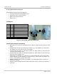
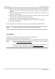
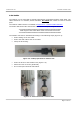
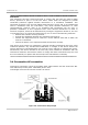
The outdoor unit shall be connected to a protective earth with not less than 10 AWG
conductors having green-yellow insulation. The following figure shows the grounding cable
from outdoor unit external screw to adjacent grounding rod. The cable should be long
enough to reach from the mounting pole to the grounding rod with 3 to 6 feet extra to allow
for strain relief.
Figure 2-8: Ground Connection to Outdoor Unit
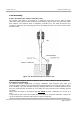
Protection from lightning
US National Electric Department of Energy Handbook 1996 specifies that radio and
television lead-in cables must have adequate surge protection at or near the point of entry
to the building. The code specifies that any shielded cable from a detached antenna must
have the shield directly connected to a 10 AWG wire that connects to the building ground
electrode.
The ground wire shall be terminated with UL listed lug with a diameter of 0.2 inch (5.2
mm).
The ground lug will need to be suitable for terminating on aluminum materials, such as the
use of an aluminum connector and aluminum ground conductor.