
Installation and Operation Instructions


Telrad Networks Ltd. BreezeAIR Installation Guide
Page 11 of 29
2
2
.
.
3
3
.
.
2
2
.
.
2
2
A
A
d
d
v
v
a
a
n
n
c
c
e
e
d
d
m
m
o
o
u
u
n
n
t
t
i
i
n
n
g
g
k
k
i
i
t
t
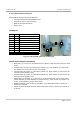
BreezeAIR advanced mounting kit features:
Azimuth and Elevation Adjustable Mount
Suitable for pole or wall mounting
Made of Die Cast Aluminum
Heavy duty
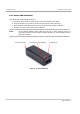
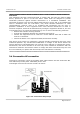
Packing list
Item Qty Description
1 1 MK1 (End Mounting Member)
2 1 MK2 (Middle Mounting Member)
3 1 MK3 (base Member)
4 1 MK4 (Back Member)
5 1 Pole 1"-4" (not supplied)
6 6 Helical Spring Lock Washer 5/16
7 6 Plain Washer 5/16
8 4 Hex Cap Screw 5/16-18 x 1"
9 2 Hex Cap Screw 5/16-18 x 5"
Figure 2-4: BreezeAIR advanced mounting kit
Advanced mounting kit installation
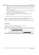
• Place MK1 (1) on the unit, as illustrated in the picture. Align the holes with the screw
studs.
• Connect MK1 (1) to the unit with spring washers (6), plain washers (7) and screws
(8). Tighten the screws at a torque of 30 Lbs·In.
• Connect MK2 (2) to MK1 (1) with spring washer (6), plain washer (7) and screw (8).
Leave the screw slightly loose.
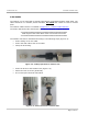
• Connect MK3 (3) to MK1 (2) with spring washer (6), plain washer (7) and screw (8).
Leave the screw slightly loose.
• Attach MK3 (3) and MK4 (4) to the pole (5) as illustrated, and connect them using
spring washers (6), plain washers (7) and screws (9). Close screws (9) together (in
turns), up to tightening torque of 30 Lbs·In.
• Distance between ends of MK3 (3) and MK4 (4) on both sides must be equal. No
skewness is allowed.
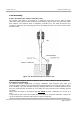
• Adjust the desired angle, and fully tighten the loose screws (of MK2) at a torque of
30 Lbs·In.
1
2
3
4
5