BreezeAIR Installation and Operation Instructions September 2021 The information contained in this document is of commercial value, proprietary to Telrad Networks. It is conveyed to the recipient solely for the purpose of evaluation. Reproduction of this document, disclosure of its contents or any other use of the information herein is strictly forbidden unless expressly authorized in writing by Telrad Networks. Telrad Networks Ltd. 1 Bat Sheva Street P.O.
Telrad Networks Ltd. BreezeAIR Installation Guide Notices Radio Frequency Statement BreezeAIR has been tested and found to comply with part 15 of the FCC rules and EN 301 489-1 rules. These limits are designed to provide reasonable protection against harmful interference when the equipment is operated in a residential environment notwithstanding use in commercial, business and industrial environments.
Telrad Networks Ltd. BreezeAIR Installation Guide R&TTE Declaration on Conformity Hereby, Telrad Networks Ltd, declares that BreezeAIR is in compliance with the essential requirements and other relevant provisions of Directive 1999/5/EC. The declaration of conformity may be consulted through Telrad Networks Ltd., 1 Bat Sheva Street, Lod 7120101, ISRAEL.
Telrad Networks Ltd. BreezeAIR Installation Guide TABLE OF CONTENTS NOTICES................................................................................................................. 2 1. 1.1 2. INTRODUCTION ............................................................................................. 6 BREEZEAIR APPLICATIONS ..................................................................................... 6 INSTALLATION ...........................................................................
Telrad Networks Ltd. BreezeAIR Installation Guide TABLE OF FIGURES Figure 1-1: BreezeAIR PTMP (blue) and PTP (red) .......................................................... 6 Figure 2-1: General System View ................................................................................. 7 Figure 2-2: BreezeAIR - General Installation Scheme ...................................................... 8 Figure 2-3: BreezeAIR basic mounting kit....................................................................
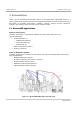
Telrad Networks Ltd. BreezeAIR Installation Guide 1. Introduction Thank you for purchasing BreezeAIR solution. Telrad Networks's BreezeAIR series is a carrier-grade point-to-point and Point-to-multipoint broadband wireless solution that sets a benchmark of unrivaled performance, reliability, capacity, latency and RF robustness, making it the ultimate choice for future-proof wireless system. 1.
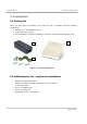
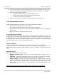
Telrad Networks Ltd. BreezeAIR Installation Guide 2. Installation 2.1 Packing list When you first open the package, verify that the unit is complete with the following components: 1. Outdoor Unit – BreezeAIR MU or SU. 2. Indoor PoE power supply. 3. Pole mounting kit (will not be added for units that require advanced mounting kit). 2 1 3 Figure 2-1: General System View 2.
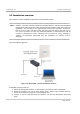
Telrad Networks Ltd. BreezeAIR Installation Guide 2.3 Installation overview This section provides installation information for BreezeAIR system. Note: Outdoor units and antennas should be installed ONLY by experienced installation professionals who are familiar with local building and safety codes and, wherever applicable, are licensed by the appropriate government regulatory authorities.
Telrad Networks Ltd. BreezeAIR Installation Guide 4) Connect the Outdoor-to-Indoor shielded CAT5 cable to the Outdoor unit and route it to the selected location of the PoE. Assemble the enclosed connector on the cable. 5) Mount the Indoor POE and connect: Outdoor-to-Indoor cable to the ‘PWR LAN-OUT’ port. CAT5 Ethernet cable (from network) to the ‘LAN-IN’ port. AC Input to the power (100-240VAC). 6) Align the antenna and secure the unit by fastening the mounting screws. 2.3.
Telrad Networks Ltd. BreezeAIR Installation Guide 2.3.2 Mounting Note: A distance of at least 250cm between the equipment and all persons should be maintained during the operation of the equipment. Une distance d'au moins 250cm entre l'équipement et toutes les personnes devraient être maintenues pendant le fonctionnement de l'équipement 2.3.2.
Telrad Networks Ltd. BreezeAIR Installation Guide 2.3.2.
Telrad Networks Ltd. BreezeAIR Installation Guide 2.3.3 Antennas 2.3.3.1 General BreezeAIR system supports two types of antennas: Integrated antenna External antenna Selecting the antenna model is according to the required range and performance. Note: To comply with the regulation EIRP limits, the outdoor unit-transmit power needs to be adjusted according to the installed antenna gain. Therefore a professional installation of the transmitter is required.
Telrad Networks Ltd. BreezeAIR Installation Guide FCC - 5.8 GHz IMPORTANT! Antennas must be selected from a list of Telrad Networks approved antennas. Please refer to Appendix C – FCC approved antennas. It is the responsibility of the installer to ensure that when using the outdoor antenna kits in the United States (or where FCC rules apply), only those antennas certified with the product are used.
Telrad Networks Ltd. BreezeAIR Installation Guide (2) High power point-to-point and point-to-multipoint operations (both fixed and temporaryfixed rapid deployment) may employ transmitting antennas with directional gain up to 26 dBi without any corresponding reduction in the maximum conducted output power or spectral density. Corresponding reduction in the maximum conducted output power and peak power spectral density should be the amount in decibels that the directional gain of the antenna exceeds 26 dBi.
Telrad Networks Ltd. BreezeAIR Installation Guide 2.3.4 Alignment Power up the unit: 1. Plug the Power Supply into a wall outlet or other standard AC power source. This is only for use prior to permanent mounting, so any available wall outlet in close proximity to your mounting location is suitable. 2. Connect the Outdoor-to-Indoor cable to the PoE ‘PWR LAN-OUT’ port (this port supplies 48 VDC in addition to the Ethernet data). BreezeAIR is aligned using 2 methods: 2.3.4.1 Using the WEB interface 1.
Telrad Networks Ltd. BreezeAIR Installation Guide 3. Take the unit to the selected location and align the antenna in the link’s direction. Listen to the buzzer tone level. Any sound (fast, medium or slow) indicates a reception. 4. Change and rotate the antenna to the left, right, up and down, scanning for the maximum reception point. 5. After the scan is complete, align the antenna to the location where the buzzer beeps at the fast rate, indicating the maximum reception. 6.
Telrad Networks Ltd. BreezeAIR Installation Guide 2.3.6 Cables The outdoor unit is connected to straight CAT5 Gauge 24-shielded outdoor rated cable. The cable should be UV resistant, flame retardant, UL listed and contain at least 4 twisted pairs. The outdoor cables scheme is indicated in Appendix A – Outdoor Cables Scheme. The Indoor PoE Outlet side and Outdoor Unit side are crimped using RJ-45 tool.
Telrad Networks Ltd. BreezeAIR Installation Guide 2.3.7 Indoor POE installation The indoor PoE is assembled as follows: 1. Crimp the RJ-45 Plugs on cable ends to form the Outdoor Unit cable. 2. Plug the Outdoor Unit cable to the RJ-45 Jack marked “PWR LAN-OUT”. 3. Plug standard CAT5 cable from the PC to the RJ-45 Jack marked “LAN-IN”. 4. Plug the AC Input to the power (100-240VAC).
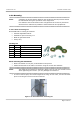
Telrad Networks Ltd. BreezeAIR Installation Guide 2.3.8 Grounding 2.3.8.1 Grounding the outdoor unit (MU /SU) The outdoor unit shall be connected to a protective earth with not less than 10 AWG conductors having green-yellow insulation. The following figure shows the grounding cable from outdoor unit external screw to adjacent grounding rod. The cable should be long enough to reach from the mounting pole to the grounding rod with 3 to 6 feet extra to allow for strain relief.
Telrad Networks Ltd. BreezeAIR Installation Guide FCC Notice This equipment has been tested and found to comply with the limits for Class B digital device, pursuant to part 15 of the FCC Rules. These limits are designed to provide reasonable protection against harmful interference in a residential installation.
Telrad Networks Ltd. BreezeAIR Installation Guide 2.5 Synchronization BreezeAIR is designed to work with co-located radios. This means that two or more units can be mounted close to each other. Time synchronization allows reusing frequencies between co-located links and configured with the Link Manager advanced window. The synchronization signal is generated by an external GPS (1 PPS) when synchronizing multiple towers, or by a master MU when synchronizing units on the same tower.
Telrad Networks Ltd. BreezeAIR Installation Guide 3. BreezeAIR Technical Specifications Radio Radio Frequency BreezeAIR ACE 4.8-6.1GHz Net Throughput 2x2 – up to 750Mbps BreezeAIR 8000 MIMO BreezeAIR 8000 SISO 700MHz, 900MHz, 2.0-2.3GHz, 2.3-2.7GHz, 3.3-3.8GHz, 4.44.8GHz, 4.8-6.0GHz, 6.0-7.0GHz, 7.0-8.0GHz, 10.0-10.
Telrad Networks Ltd. BreezeAIR Installation Guide 4. BreezeAIR NET Throughput (Mbps) 4.1 BreezeAIR 8000 MIMO & SISO 50MHz 40MHz 28MHz 20MHz 14MHz 10MHz 7MHz 5MHz 3.5MHz BreezeAIR 8000 MIMO BPSK 1/2 30.6 26.8 16.1 11.5 8.8 6.3 3.2 2.3 1.6 QPSK 1/2 61.7 54.1 32.6 23.3 15.3 10.9 6.9 4.9 3.4 QPSK 3/4 92.6 81.2 48.7 34.8 23.4 16.7 10.5 7.5 5.3 16QAM 1/2 124.7 109.4 65.2 46.6 31.4 22.4 14.1 10.1 7.1 16QAM 3/4 185.0 162.3 98.4 70.3 47.0 33.6 21.4 15.3 10.
Telrad Networks Ltd. BreezeAIR Installation Guide 5. Appendix A – outdoor cables scheme Figure 5-1: Outdoor Cables Scheme Note: In order to comply with 100 meter CAT5 cable Pins 1,2 must be a twisted pair wire. Pins 3,6 must be a twisted pair wire. Pins 4,5 must be a twisted pair wire. Pins 7,8 must be a twisted pair wire. Recommended cable length: 10/100/1000Base-T – 75m. 10/100Base-T – 100m.
Telrad Networks Ltd. BreezeAIR Installation Guide 6. Appendix B – RF channel lists 6.1 BreezeAIR 8000 FCC operating Band: 5725-5850MHz FCC ID: QQ2-WA8K5X Channel No.
Telrad Networks Ltd. BreezeAIR Installation Guide 6.3 BreezeAIR 8000 FCC operating Band: 2496-2690MHz FCC ID: QQ2-WA8K25X 5MHz channel – 2500 – 2687 MHz. 10MHz channel – 2501 – 2685 MHz. 14MHz channel – 2503 – 2682 MHz. 20MHz channel – 2506 – 2680 MHz. 6.4 BreezeAIR ACE FCC operating Band: 5725-5850MHz FCC ID: ARA-BACE5X Hardware Version Identification Number (HVIN) - BACE5X Firmware Version Identification Number (FVIN) - x15.xxxx (x = any number between 0-9) Channel No.
Telrad Networks Ltd. BreezeAIR Installation Guide 7. Appendix C – FCC approved antennas Antenna Type Flat panel Dish Model Gain Dimension [dBi] [mm] B-5X23S010F 23 305x305x15 B-5X23D009F 23 371x371x40 B-5X23D010F 23 305x305x40 B-5X17D020F 17.5 200x200x15 B-5X15D120S 15 430x165x35 B-5X17D090S 17 430x165x35 B-5X17D060S 17 430x165x35 B-5X15V120S 15 450x165x35 B-5X17V090S 17 450x165x35 B-5X18V060S 18 450x165x35 B-5X29D005P 28 (27 dBi @ 4.
Telrad Networks Ltd. BreezeAIR Installation Guide 8. Appendix D – Lightning Protection All outdoor wireless equipment is susceptible to lightning damage from a direct hit or induced current from a near strike. A direct lightning strike may cause serious damage even if these guidelines are followed. Lightning protection and grounding practices in local and national electrical codes serve to minimize equipment damage, service outages, and serious injury. Possible reasons for lightning damage: 1.
Telrad Networks Ltd. BreezeAIR Installation Guide 8.1 BreezeGuard lightning protection Telrad Networks BreezeGuard is 1000Mbps PoE Outdoor Surge Protector, is designed to protect BreezeAIR PoE network from lightning over-voltage, transient over-voltage and static discharge. The protector implements multi-level protection circuit with advanced manufacturing process, and has excellent performance on discharge current, limiting voltage, response time, stability and over-all reliability.