
User's Manual
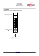
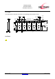

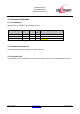
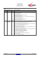
Table Of Contents
- 1 Introduction
- 2 Block Diagram
- 3 Application Interface
- 3.1 Power Supply
- 3.2 Power-up / -down Slew-Rate
- 3.3 Reset
- 3.4 Supply Voltage Monitor
- 3.5 Serial Interface
- 3.6 GPIO Interface
- 3.7 I2C Interface0F
- 3.8 SPI Serial Peripheral Interface1F
- 1.1
- 3.9 Bluetooth Radio Interface
- 3.10 WLAN Coexistence Interface2F
- 3.11 Slow Clock Interface
- 3.12 Test Mode Enable
- 3.13 Pin Strapped System Memory Boot Mode Invocation
- 3.14 Operating in a Power-Switched Environment
- 3.15 Serial Wire Interface
- 4 Module Pins
- 5 Electrical Characteristics
- 6 Mechanical Characteristics
- 1
- 7 Application Diagram
- 8 Approvals/Certifications
- 9 Related Documents
- 10 Packing
- 11 Ordering Information

BlueMod+SR/AI
BlueMod+SR/AP
Hardware Reference
Release r04d01 www.stollmann.de Page 63 of 65
11 Ordering Information
11.1 Part Numbers
BlueMod+SR is available in the following variants:
Name Antenna Order No. MOQ /
units
Comments
BlueMod+SR/AI internal 53231-xx 50
BlueMod+SR/AP external 53252-xx 500
BlueEva+SR Internal 53249-xx 1 Evaluation Kits
Other variants on request, please contact Stollmann sales department.
11.2 Standard Packing Unit
The standard packing unit is 500 pieces Tape and Reel
11.3 Evaluation Kit
The kit BlueEva+SR is available to evaluate functionality and start your firmware implementation.