
User's Manual

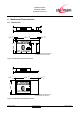
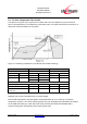
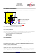
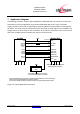
Table Of Contents
- 1 Introduction
- 2 Block Diagram
- 3 Application Interface
- 3.1 Power Supply
- 3.2 Power-up / -down Slew-Rate
- 3.3 Reset
- 3.4 Supply Voltage Monitor
- 3.5 Serial Interface
- 3.6 GPIO Interface
- 3.7 I2C Interface0F
- 3.8 SPI Serial Peripheral Interface1F
- 1.1
- 3.9 Bluetooth Radio Interface
- 3.10 WLAN Coexistence Interface2F
- 3.11 Slow Clock Interface
- 3.12 Test Mode Enable
- 3.13 Pin Strapped System Memory Boot Mode Invocation
- 3.14 Operating in a Power-Switched Environment
- 3.15 Serial Wire Interface
- 4 Module Pins
- 5 Electrical Characteristics
- 6 Mechanical Characteristics
- 1
- 7 Application Diagram
- 8 Approvals/Certifications
- 9 Related Documents
- 10 Packing
- 11 Ordering Information

BlueMod+SR/AI
BlueMod+SR/AP
Hardware Reference
Release r04d01 www.stollmann.de Page 47 of 65
6.3 Re-flow Temperature-Time Profile
The data here is given only for guidance on solder and has to be adapted to your process and
other re-flow parameters for example the used solder paste. The paste manufacturer provides a re-
flow profile recommendation for his product.
Figure 17: Soldering Temperature-Time Profile (For Reflow Soldering)
Preheat Main Heat Peak
tsmax tLmax tpmax
Temperature Time Temperature Time Temperature Time
[°C] [sec] [°C] [sec] [°C] [sec]
150
100
217 90 260
10
230 50
Average ramp-up rate [°C / sec] 3
Average ramp-down rate [°C / sec] 6
Max. Time 25°C to Peak
Temperature
[min.] 8
Opposite side re-flow is prohibited due to module weight.
Devices will withstand the specified profile and will withstand up to 1 re-flows to a maximum
temperature of 260°C. The reflow soldering profile may only be applied if the BlueMod+SR resides
on the PCB side looking up. Heat above the solder eutectic point while the BlueMod+SR is
mounted facing down may damage the module permanently.