
User's Manual
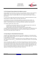

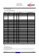
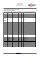
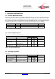
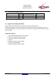
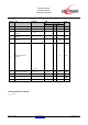
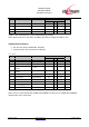
Table Of Contents
- 1 Introduction
- 2 Block Diagram
- 3 Application Interface
- 3.1 Power Supply
- 3.2 Power-up / -down Slew-Rate
- 3.3 Reset
- 3.4 Supply Voltage Monitor
- 3.5 Serial Interface
- 3.6 GPIO Interface
- 3.7 I2C Interface0F
- 3.8 SPI Serial Peripheral Interface1F
- 1.1
- 3.9 Bluetooth Radio Interface
- 3.10 WLAN Coexistence Interface2F
- 3.11 Slow Clock Interface
- 3.12 Test Mode Enable
- 3.13 Pin Strapped System Memory Boot Mode Invocation
- 3.14 Operating in a Power-Switched Environment
- 3.15 Serial Wire Interface
- 4 Module Pins
- 5 Electrical Characteristics
- 6 Mechanical Characteristics
- 1
- 7 Application Diagram
- 8 Approvals/Certifications
- 9 Related Documents
- 10 Packing
- 11 Ordering Information

BlueMod+SR/AI
BlueMod+SR/AP
Hardware Reference
Release r04d01 www.stollmann.de Page 27 of 65
5 Electrical Characteristics
5.1 Absolute Maximum Ratings
Stresses beyond those listed under “Absolute Maximum Ratings” may cause permanent damage
to the device. These are stress ratings only, and functional operation of the device at these or any
other conditions beyond those indicated under “Electrical Requirements” is not implied. Exposure
to absolute-maximum-rated conditions for extended periods may affect device reliability.
Item Symbol Absolute Maximum Ratings Unit
Supply voltage VSUP -0,3 to +3,6 V
Voltage on any pin V
Pin
-0,3 to VSUP +0,4 V
Table 6: Absolute Maximum Ratings
5.2 Electrical Requirements
VSUP = 3,3V, T
amb
= 25°C if nothing else stated
Item Condition Limit Unit
Min Typ Max
Frequency Range 2400 2483.5 MHz
Load impedance
Measured with network
analyzer in the frequency
range at antenna pin
50 Ohm
Output return loss
Receive Mode to 50Ω load
Transmit Mode to 50Ω load
-10
-10
dBm
Table 7: Electrical Requirements
5.3 Operating Conditions
T
amb
= 25°C
Item Condition Limit Unit
Min Typ Max
Supply voltage VSUP
2,5 3,3 3,6 V
DC
Ripple on VSUP
Ripple frequency ≤10MHz
10 mV
rms
Table 8: DC Operating Conditions