
User's Manual


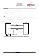
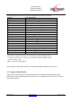
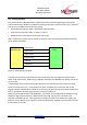
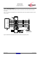
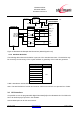
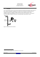
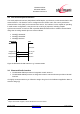
Table Of Contents
- 1 Introduction
- 2 Block Diagram
- 3 Application Interface
- 3.1 Power Supply
- 3.2 Power-up / -down Slew-Rate
- 3.3 Reset
- 3.4 Supply Voltage Monitor
- 3.5 Serial Interface
- 3.6 GPIO Interface
- 3.7 I2C Interface0F
- 3.8 SPI Serial Peripheral Interface1F
- 1.1
- 3.9 Bluetooth Radio Interface
- 3.10 WLAN Coexistence Interface2F
- 3.11 Slow Clock Interface
- 3.12 Test Mode Enable
- 3.13 Pin Strapped System Memory Boot Mode Invocation
- 3.14 Operating in a Power-Switched Environment
- 3.15 Serial Wire Interface
- 4 Module Pins
- 5 Electrical Characteristics
- 6 Mechanical Characteristics
- 1
- 7 Application Diagram
- 8 Approvals/Certifications
- 9 Related Documents
- 10 Packing
- 11 Ordering Information

BlueMod+SR/AI
BlueMod+SR/AP
Hardware Reference
Release r04d01 www.stollmann.de Page 20 of 65
3.10 WLAN Coexistence Interface
3
For implementing WLAN Coexistence with CSR’s Wi-Fi solution the Unity 3e+ solution is
implemented. For non-CSR WiFi solutions only the 3 Signals BT_ACTIVE (BT-ACT), BT_STATUS
(BT-STAT) and WLAN_DENY (WLAN-DNY) are used.
BlueMod+SR
WiFi Device
BT-ACT
BT-STAT
WLAN-DNY
BT-PER
Figure 9: Unity 3e+ Coexistence
If this interface is not used, these signals may be left unconnected.
If your application needs to use these signals, ask Stollmann for support.
3.11 Slow Clock Interface
Consumption of power during power-down modes can be reduced by feeding the module with a
32,768 kHz slow clock at pin SLCK.
SLCK specification:
• 32,768 kHz typ., 30 kHz min., 35 kHz max. Duty cycle 30...70%.
• Signal must be square wave, at VSUP-level (see note below) and present as long as VSUP
is powered.
The module’s firmware will detect the presence of a slow clock during the boot process and switch
behavior appropriately. This check does only apply for presence of some clock; it is not checked if
the clock frequency is in the valid range required by CSR8811 (30kHz ... 35kHz).
If this signal is not used, to minimize risk of erroneous pulse detection in noisy environments,
Stollmann recommends the connection of A-6 to GND (direct connection or pull-down resistor).
Note: Since SLCK is fed to both the STM32 and the CSR8811, the electrical characteristics as
described in Table 11 (V
LSEH
) and Table 12 (V
IH
) apply at the same time.
3.12 Test Mode Enable
This functionality is reserved. Leave pin TESTMODE# open.
3
subject to firmware support, contact Stollmann for current status