
User's Manual


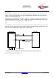
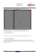
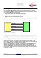
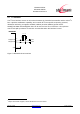
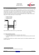
Table Of Contents
- 1 Introduction
- 2 Block Diagram
- 3 Application Interface
- 3.1 Power Supply
- 3.2 Power-up / -down Slew-Rate
- 3.3 Reset
- 3.4 Supply Voltage Monitor
- 3.5 Serial Interface
- 3.6 GPIO Interface
- 3.7 I2C Interface0F
- 3.8 SPI Serial Peripheral Interface1F
- 1.1
- 3.9 Bluetooth Radio Interface
- 3.10 WLAN Coexistence Interface2F
- 3.11 Slow Clock Interface
- 3.12 Test Mode Enable
- 3.13 Pin Strapped System Memory Boot Mode Invocation
- 3.14 Operating in a Power-Switched Environment
- 3.15 Serial Wire Interface
- 4 Module Pins
- 5 Electrical Characteristics
- 6 Mechanical Characteristics
- 1
- 7 Application Diagram
- 8 Approvals/Certifications
- 9 Related Documents
- 10 Packing
- 11 Ordering Information

BlueMod+SR/AI
BlueMod+SR/AP
Hardware Reference
Release r04d01 www.stollmann.de Page 17 of 65
VDDIO
(+1.2V .. +3.6V)
BlueMod+SR
GND
D-2
F-4
F-3
D-7
UART_RXD
UART_TXD
UART_CTS#
UART_RTS#
10µ+100n+1n
SN74AVC4T245
User Host System
VSUP
XC6204-3.3
VOUT
VSS
VIN
CE
1µ
100k
100k
VCCB
1B1
1B2
2B1
2B2
2A2
2A1
1A2
1A1
VCCA
1DIR
1OE
2DIR
2OE
(GPIO, Out,
no pu/pd)
(GPIO, Out,
no pu/pd)
TXD
RTS#
RXD
CTS#
+5VDC
OE_DRV#
BT_ENABLE
VDD_HOST (+1.2 .. +3.6V)
+3V3_switched
Figure 6: BlueMod+SR Example Serial Interface (Mixed Signal Level)
3.5.2 Baudrate Deviation
The following table shows the deviation in percent of the standard data rates. The deviation may
be caused by the inaccuracy of the crystal oscillator or granularity of the baud rate generator.
Data Rate (bits/s) Deviation (%)
9600
±1%
19200
38400
57600
115200
230400
460800
921600
Table 3: Baudrates and Deviations
Note: The total deviation of sender and receiver shall not exceed 2.5 % to prevent loss of data.
3.6 GPIO Interface
It is possible to use the programmable digital I/Os GPIO[0:8] on the BlueMod+SR. Their behavior
has to be defined project specific in the firmware.
Unused GPIO pins can be left unconnected.