
User's Manual


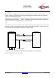
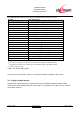
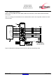
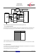
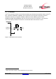
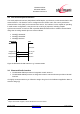
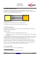
Table Of Contents
- 1 Introduction
- 2 Block Diagram
- 3 Application Interface
- 3.1 Power Supply
- 3.2 Power-up / -down Slew-Rate
- 3.3 Reset
- 3.4 Supply Voltage Monitor
- 3.5 Serial Interface
- 3.6 GPIO Interface
- 3.7 I2C Interface0F
- 3.8 SPI Serial Peripheral Interface1F
- 1.1
- 3.9 Bluetooth Radio Interface
- 3.10 WLAN Coexistence Interface2F
- 3.11 Slow Clock Interface
- 3.12 Test Mode Enable
- 3.13 Pin Strapped System Memory Boot Mode Invocation
- 3.14 Operating in a Power-Switched Environment
- 3.15 Serial Wire Interface
- 4 Module Pins
- 5 Electrical Characteristics
- 6 Mechanical Characteristics
- 1
- 7 Application Diagram
- 8 Approvals/Certifications
- 9 Related Documents
- 10 Packing
- 11 Ordering Information

BlueMod+SR/AI
BlueMod+SR/AP
Hardware Reference
Release r04d01 www.stollmann.de Page 14 of 65
The following table shows the pin states of BlueMod+SR during reset active.
Pin Name State: BlueMod+SR
EXT-RES# I/O with pull-up
(1)
and 100n to GND – use open drain
SLCK Input with weak pull-down
(2)
UART-TXD Input floating
UART-RXD Input floating
UART-RTS# Input with pull-up resistor 470kΩ
(4)
UART-CTS# Input floating
IUR-OUT# Input with pull-up resistor 470kΩ
(4)
IUR-IN# Input floating
GPIO[0:4, 6:7] Input floating
GPIO[5] Input with pull-up
(1)
GPIO[8] Output (JTDO)
BT-ACT Input with weak pull-up
(2)
BT-STAT Input with weak pull-up
(2)
WLAN-DNY Input with weak pull-up
(2)
BT-PER Input with weak pull-up
(2)
TESTMODE# Input floating
BOOT0 Input with pull-down resistor 100kΩ
(4)
SWDIO Input with pull-up
(1)
SWCLK Input with pull-down
(1)
(1)
pull-up, pull-down: R
PU,
R
PD
is typ. 40kΩ (30kΩ to 50kΩ)
(2)
weak pull-up, pull-down: See Table 12: DC characteristics, digital IO (CSR8811 related)
(3)
strong pull-up, pull-down: See Table 12: DC characteristics, digital IO (CSR8811 related)
(4)
a discrete resistor is used
Table 2: Pin States during Reset
The pin states as indicated in Table 2 are kept until hardware initialization has started.
3.4 Supply Voltage Monitor
Supply-under-voltage detection is implemented using the STM32 embedded supply voltage
monitor PVD. When VSUP falls below a threshold V
PVD
(programmed to 2,38V ± 0,1V), a system
reset will be asserted.