
User's Manual


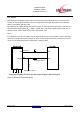
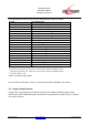
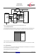
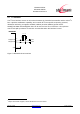
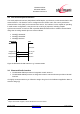
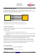
Table Of Contents
- 1 Introduction
- 2 Block Diagram
- 3 Application Interface
- 3.1 Power Supply
- 3.2 Power-up / -down Slew-Rate
- 3.3 Reset
- 3.4 Supply Voltage Monitor
- 3.5 Serial Interface
- 3.6 GPIO Interface
- 3.7 I2C Interface0F
- 3.8 SPI Serial Peripheral Interface1F
- 1.1
- 3.9 Bluetooth Radio Interface
- 3.10 WLAN Coexistence Interface2F
- 3.11 Slow Clock Interface
- 3.12 Test Mode Enable
- 3.13 Pin Strapped System Memory Boot Mode Invocation
- 3.14 Operating in a Power-Switched Environment
- 3.15 Serial Wire Interface
- 4 Module Pins
- 5 Electrical Characteristics
- 6 Mechanical Characteristics
- 1
- 7 Application Diagram
- 8 Approvals/Certifications
- 9 Related Documents
- 10 Packing
- 11 Ordering Information

BlueMod+SR/AI
BlueMod+SR/AP
Hardware Reference
Release r04d01 www.stollmann.de Page 12 of 65
3 Application Interface
3.1 Power Supply
BlueMod+SR require a power supply with the following characteristics:
Typical: 3,3V
DC
, min.: 2,5V
DC
, max.: 3.6V
DC
, low noise (≤ 10mV
rms
), > 80mA peak
For optimal performance a stable supply is recommended. If a regulator is to be used, it should be
a fast linear regulator placed as close as possible to the VSUP pins (E-6, F-6). Functionality has
been verified with the following types: TOREX: XC6204x332xx or XC6401xx42xx.
If the regulator cannot be placed close to the BlueMod+SR, it is recommended to place an
additional low ESR capacitor with at least 10µF as close as possible to the VSUP pins (E-6, F-6 or
C-1).
BlueMod+SR
XC6204-3.3
C-1,E-6,F-6
VSUP
GND:
A-7,E-7,F-7,B-[5:8],
C-[5:8],D-8,E-8,F-8
10µ + 100n + 1n
1µ
VOUT
VSS
VIN
CE
5 1
3
2
+5VDC
Figure 2: BlueMod+SR Example Power Supply
3.2 Power-up / -down Slew-Rate
Parameter
Min
Max
Unit
VSUP rise time rate 0 ∞
µs/V
VSUP fall time rate 20 ∞
Table 1: Power up/down Slew Rate Requirements