
User's Manual

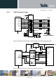


Table Of Contents
- 1 Introduction
- 2 General Product Description
- 3 Application Interface
- 3.1 Power Supply
- 3.2 Reset
- 3.3 Serial Interface
- 3.4 GPIO Interface
- 3.5 I2C Interface 0F
- 3.6 SPI Serial Peripheral Interface
- 3.7 Bluetooth Radio Interface
- 1.1
- 3.8 NFC Function
- 3.9 Slow Clock Interface
- 3.10 Test Mode
- 3.11 Operating in a Power-Switched Environment
- 3.12 Serial Wire Debug Interface
- 3.13 DC/DC Converter
- 4 Module Pins
- 5 Electrical Characteristics
- 6 Mechanical Characteristics
- 7 Application Diagram
- 8 Compliances
- 9 Packing
- 10 Ordering Information
- 11 Safety Recommendations
- 12 Document History

BlueMod+S42 Hardware User Guide
1VV0301303 Rev.3 – 2016-08-22
Reproduction forbidden without written authorization from Telit Communications S.p.A. - All Rights Reserved.
Page 29 of 62
C
L
= (C1+C
pin
+C
s
) * (C2+C
pin
+C
s
) / (C1+C2+2*C
pin
+2*Cs), or
C1, C2 = (2*C
L
– C
pin
– C
s
)
C
pin
: see Table 5
C
s
: stray capacitance, depends on layout
Figure 11: BlueMod+S42 connection of external XTAL
3.10 Test Mode
For homologation purposes the ability of test mode operation like “BlueMod+S42_Testmode”
or “Direct two wire UART Testmode” (DTM) is mandatory. The Direct Test Mode (as
defined by the Bluetooth SIG) and BlueMod+S42_Testmode are part of the BlueMod+S42
TIO-Firmware. Please refer to tbd.
For enabling the different test modes the BlueMod+S42 provides two IO pins.
• The pin Testmode is low active. Active in the following table means connect to GND.
• The pin Boot0 is high active. Active in the following table means connect to VDD.
• The other two combinations start the bootloader for firmware update of the
programmed firmware. These two modes are not scope of this document.
Table 6 shows the possible combinations:
Testmode#
Boot0
Mode
Active Inactive Testmode
Active Active DTM
Inactive Active Start Bootloader
Inactive Inactive Firmware Update
Table 6: Testmode# / Boot0 Logic
XL-IN
BlueMod+S42
A-6
Slow Clock
XL-OUT
A-5
32,768kHz
CL: 9pF
C1
C2
C1, C2 ~ 12pF