
User's Manual

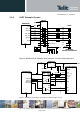


Table Of Contents
- 1 Introduction
- 2 General Product Description
- 3 Application Interface
- 3.1 Power Supply
- 3.2 Reset
- 3.3 Serial Interface
- 3.4 GPIO Interface
- 3.5 I2C Interface 0F
- 3.6 SPI Serial Peripheral Interface
- 3.7 Bluetooth Radio Interface
- 1.1
- 3.8 NFC Function
- 3.9 Slow Clock Interface
- 3.10 Test Mode
- 3.11 Operating in a Power-Switched Environment
- 3.12 Serial Wire Debug Interface
- 3.13 DC/DC Converter
- 4 Module Pins
- 5 Electrical Characteristics
- 6 Mechanical Characteristics
- 7 Application Diagram
- 8 Compliances
- 9 Packing
- 10 Ordering Information
- 11 Safety Recommendations
- 12 Document History

BlueMod+S42 Hardware User Guide
1VV0301303 Rev.3 – 2016-08-22
Reproduction forbidden without written authorization from Telit Communications S.p.A. - All Rights Reserved.
Page 28 of 62
3.9 Slow Clock Interface
Even though an external slow clock is not required for BLE operation, consumption of power
during power-down modes can be reduced by connecting an XTAL (32,768kHz) and two
capacitors C1, C2 at pins XL-IN and XL-OUT.
3.9.1 32,768 kHz Crystal Oscillator Specification (32k XOSC)
Symbol Item Condition Limit Unit
Min Typ Max
f
NOM
Crystal Frequency T
amb
= 25°C 32,768 kHz
f
TOL
Frequency Tolerance for
BLE applications
including temperature
and aging
(1)
+/-250 ppm
C
L
Load Capacitance 12,5 pF
C0 Shunt Capacitance 2 pF
R
S
Equivalent Series
Resistance
100 kΩ
P
D
Drive Level 1 µW
C
pin
Input Cap. On XL-IN and
XL-OUT
4 pF
(11) adjust crystal frequency by choosing correct value for C1, C2 (value depends on C
L
of
crystal and layout)
Table 5: 32,768kHz Crystal Oscillator
The module’s firmware will detect the presence of a slow clock during the boot process and
switch behavior appropriately.
3.9.2 Connection of an External 32,768 kHz Crystal
Connect the 32,768 kHz crystal and two capacitors C1, C2 at pins A-6 (XL-IN) and A-5 (XL-
OUT). The crystal has to comply with specifications given in Table 5. The exact value of
C1 and C2 depends on the crystal and the stray capacitance of the layout. Select C1, C2 such
that the slow clock oscillator operates at the exact frequency at room temperature (25°C). C1
and C2 shall be of equal capacity. The crystal and the capacitors shall be located as close as
possible to pins A-5, A-6.