
User's Manual

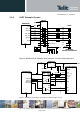


Table Of Contents
- 1 Introduction
- 2 General Product Description
- 3 Application Interface
- 3.1 Power Supply
- 3.2 Reset
- 3.3 Serial Interface
- 3.4 GPIO Interface
- 3.5 I2C Interface 0F
- 3.6 SPI Serial Peripheral Interface
- 3.7 Bluetooth Radio Interface
- 1.1
- 3.8 NFC Function
- 3.9 Slow Clock Interface
- 3.10 Test Mode
- 3.11 Operating in a Power-Switched Environment
- 3.12 Serial Wire Debug Interface
- 3.13 DC/DC Converter
- 4 Module Pins
- 5 Electrical Characteristics
- 6 Mechanical Characteristics
- 7 Application Diagram
- 8 Compliances
- 9 Packing
- 10 Ordering Information
- 11 Safety Recommendations
- 12 Document History

BlueMod+S42 Hardware User Guide
1VV0301303 Rev.3 – 2016-08-22
Reproduction forbidden without written authorization from Telit Communications S.p.A. - All Rights Reserved.
Page 27 of 62
• Integrated automatic collision resolution, CRC and parity functions
3.8.1 NFCT Antenna Recommendations
The NFCT antenna coil must be connected differential between NFCANT1 and NFCANT2
pins of BlueMod+S42.
Two external capacitors C
tune1/2 connected between the NFCANTx pins and GND should be
used to tune the resonance of the antenna circuit to 13.56 MHz.
NFCANT1
BlueMod+S42
A-3
NFCANT2
A-4
C
tune1
C
tune2
C
p1
C
p2
C
int2
C
int1
NFC-Antenna
Figure 10: BlueMod+S42 NFC Antenna Tuning
=
2
(
2 × 13,56
)
×
=
=
=
=
( )
=
=
= 4
3.8.2 Power Back feeding
If the NFC antenna is exposed to a strong NFC field, power back feeding may occur. That
means, current may flow in the opposite direction on the supply due to parasitic diodes and
ESD structures.
If a battery is used that does not tolerate return current, a series diode must be placed between
the battery and the BlueMod+S42 in order to protect the battery. An ultra-low forward voltage
schottky diode should be chosen to keep the battery life reduction as small as possible.