
User's Manual

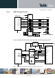


Table Of Contents
- 1 Introduction
- 2 General Product Description
- 3 Application Interface
- 3.1 Power Supply
- 3.2 Reset
- 3.3 Serial Interface
- 3.4 GPIO Interface
- 3.5 I2C Interface 0F
- 3.6 SPI Serial Peripheral Interface
- 3.7 Bluetooth Radio Interface
- 1.1
- 3.8 NFC Function
- 3.9 Slow Clock Interface
- 3.10 Test Mode
- 3.11 Operating in a Power-Switched Environment
- 3.12 Serial Wire Debug Interface
- 3.13 DC/DC Converter
- 4 Module Pins
- 5 Electrical Characteristics
- 6 Mechanical Characteristics
- 7 Application Diagram
- 8 Compliances
- 9 Packing
- 10 Ordering Information
- 11 Safety Recommendations
- 12 Document History

BlueMod+S42 Hardware User Guide
1VV0301303 Rev.3 – 2016-08-22
Reproduction forbidden without written authorization from Telit Communications S.p.A. - All Rights Reserved.
Page 22 of 62
3.3.2 UART Example Circuits
2
BlueMod+S42
GND
MAX3241
14
+3V3
22
23
2
3
7
8
4
6
1
9
TXD
RXD
RTS#
CTS#
IUR-OUT#
IUR-IN#
TXD
RXD
RTS
CTS
DTR
DSR
DCD
RI
RS232
DSUB9 (male)
DTE style connector pinout
9
4
10
5
11
6
7
8
19
13
18
12
17
16
15
F-4
D-2
D-7
F-3
B-4
D-5
UART_TXD
UART_RXD
UART_RTS#
UART_CTS#
IUR-OUT#
IUR-IN#
SHDN#
EN#
100n
100n
28
24
1
+3V3
100n
100n
100n
26
3
27
25
V+
VCC
V -
GND
C2+
C2-
C1+
C1-
220R
220R
220R
220R
220R
220R
5
SigGND
can be left open
VSUP
+3V3
Figure 6: BlueMod+S42 Example Serial Interface (RS-232) Supporting UICP
VDDIO
(+1.2V .. +3.6V)
BlueMod+S42
GND
D-2
F-4
F-3
D-7
UART_RXD
UART_TXD
UART_CTS#
UART_RTS#
10µ+100n+1n
SN74AVC4T245
User Host System
VSUP
XC6209F-3.3
VOUT
VSS
VIN
CE
1µ
100k
100k
VCCB
1B1
1B2
2B1
2B2
2A2
2A1
1A2
1A1
VCCA
1DIR
1OE
2DIR
2OE
(GPIO, Out,
no pu/pd)
(GPIO, Out,
no pu/pd)
TXD
RTS#
RXD
CTS#
+5VDC
OE_DRV#
BT_ENABLE
VDD_HOST (+1.2 .. +3.6V)
+3V3_switched
Figure 7: BlueMod+S42 Example Serial Interface (Mixed Signal Level)