
User's Manual

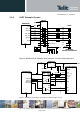


Table Of Contents
- 1 Introduction
- 2 General Product Description
- 3 Application Interface
- 3.1 Power Supply
- 3.2 Reset
- 3.3 Serial Interface
- 3.4 GPIO Interface
- 3.5 I2C Interface 0F
- 3.6 SPI Serial Peripheral Interface
- 3.7 Bluetooth Radio Interface
- 1.1
- 3.8 NFC Function
- 3.9 Slow Clock Interface
- 3.10 Test Mode
- 3.11 Operating in a Power-Switched Environment
- 3.12 Serial Wire Debug Interface
- 3.13 DC/DC Converter
- 4 Module Pins
- 5 Electrical Characteristics
- 6 Mechanical Characteristics
- 7 Application Diagram
- 8 Compliances
- 9 Packing
- 10 Ordering Information
- 11 Safety Recommendations
- 12 Document History

BlueMod+S42 Hardware User Guide
1VV0301303 Rev.3 – 2016-08-22
Reproduction forbidden without written authorization from Telit Communications S.p.A. - All Rights Reserved.
Page 21 of 62
When using the TIO firmware and applications, call control can be supported by GPIO[4].
Driving GPIO[4] to logic High level during a data transfer phase will “hang up” the
connection and disconnect the Bluetooth link. This signal may be mapped to DSR, if an
RS232-style (DTE-type) interface is used. Please refer to BlueMod+S42\Central AT
Command Reference for a functional specification. GPIO[4] can be left unconnected if this
feature is not used.
3.3.1 4-Wire Serial Interface
If the host in question is sufficiently fast, a four-wire scheme may be successful. Connect the
serial lines UART-RXD, UART-TXD as well as UART-RTS# and GND; leave UART-CTS#
open. The host is required to stop sending data within a short time after de-assertion of
UART-RTS# (there is room for up to 4 more characters at the time RTS# drops).
Attention: UICP has to be deactivated permanently in this configuration, because signal
UART-CTS# and IUR-IN# become inputs with no PU or PD if UICP is active. This would
cause floating CMOS inputs.
NOTE:
It is strongly recommended to use hardware flow control in both directions. Not using flow
control can cause a loss of data.