
User's Manual
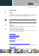
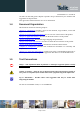


Table Of Contents
- 1 Introduction
- 2 General Product Description
- 3 Application Interface
- 3.1 Power Supply
- 3.2 Reset
- 3.3 Serial Interface
- 3.4 GPIO Interface
- 3.5 I2C Interface 0F
- 3.6 SPI Serial Peripheral Interface
- 3.7 Bluetooth Radio Interface
- 1.1
- 3.8 NFC Function
- 3.9 Slow Clock Interface
- 3.10 Test Mode
- 3.11 Operating in a Power-Switched Environment
- 3.12 Serial Wire Debug Interface
- 3.13 DC/DC Converter
- 4 Module Pins
- 5 Electrical Characteristics
- 6 Mechanical Characteristics
- 7 Application Diagram
- 8 Compliances
- 9 Packing
- 10 Ordering Information
- 11 Safety Recommendations
- 12 Document History

BlueMod+S42 Hardware User Guide
1VV0301303 Rev.3 – 2016-08-22
Reproduction forbidden without written authorization from Telit Communications S.p.A. - All Rights Reserved.
Page 20 of 62
BlueMod+S42
Host
UART-RXD
UART-TXD
UART-CTS#
UART-RTS#
IUR-IN#
IUR-OUT#
GND
Figure 4: Serial Interface Signals
The basic serial interface (with RTS/CTS flow control) uses only four signal lines (UART-
RXD, UART-TXD, UART-CTS#, UART-RTS#) and GND. IUR-IN#, IUR-OUT# and
GPIO[4] (see below) can be left unconnected.
A substantially saving of power during idle phases can be achieved (see 5.5.1) when the UICP
protocol is used (refer to UICP_UART_Interface_Control_Protocol, 30507ST10756A). This
protocol should be implemented on the host side as well. Signals IUR-IN# and IUR-OUT#
should be connected to the host (see Figure 4: Serial Interface
Signals) and may be mapped to DSR and DTR, if an RS232-style (DTE-type) interface is
used (see Figure 6).
BlueMod+S
42
Host
UART-TXD
IUR-OUT#
UART
-CTS
#
UART-RXD
IUR-IN#
UART-RTS#
IUR-OUT#
IUC
-IN#
CTS#
TXD
RXD
GND
GND
Figure 5: Five Wire Interface supporting UICP (Minimum Signals needed)
Figure 5 shows the minimal configuration to use UICP for both directions RxD and TxD. To
use this scheme, the user has to implement UICP on host side for the transmitter only to wake
up the BlueMod+S42 receiver.