
User's Manual
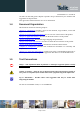


Table Of Contents
- 1 Introduction
- 2 General Product Description
- 3 Application Interface
- 3.1 Power Supply
- 3.2 Reset
- 3.3 Serial Interface
- 3.4 GPIO Interface
- 3.5 I2C Interface 0F
- 3.6 SPI Serial Peripheral Interface
- 3.7 Bluetooth Radio Interface
- 1.1
- 3.8 NFC Function
- 3.9 Slow Clock Interface
- 3.10 Test Mode
- 3.11 Operating in a Power-Switched Environment
- 3.12 Serial Wire Debug Interface
- 3.13 DC/DC Converter
- 4 Module Pins
- 5 Electrical Characteristics
- 6 Mechanical Characteristics
- 7 Application Diagram
- 8 Compliances
- 9 Packing
- 10 Ordering Information
- 11 Safety Recommendations
- 12 Document History

BlueMod+S42 Hardware User Guide
1VV0301303 Rev.3 – 2016-08-22
Reproduction forbidden without written authorization from Telit Communications S.p.A. - All Rights Reserved.
Page 18 of 62
3.1.1 Power-up Slew-Rate
Parameter Min Max Unit
VSUP rise time rate
(1)
0 60 ms
(1)
0V to 1,7V
Table 2: Power up Rise Time Requirements
3.2 Reset
BlueMod+S42 are equipped with circuitry for generating reset from three sources:
• A reset is held active, when VSUP falls below the threshold of the brownout detector
(V
BOR =
1,2V … 1,7V), and is released when VSUP rises above V
BOR
+ V
HYST
.
The brownout detector also holds the reset active during power up, until VSUP >
V
BOR
.
• A reset is generated, when VSUP is > V
BOR
and increases 300 mV or more, within
300 ms or less.
• By holding pin B-1 (EXT-RES#) at ≤ VSUP*0,3V for t
HOLDRESETNORMAL
≥ 0,2µs, an
external reset (pin reset) is generated. This pin has a fixed internal pull-up resistor
(R
PU
= 11kΩ ... 16kΩ). EXT-RES# may be left open if not used.
BlueMod+S42
E-6,F-6
VSUP
GND
+3V3
EXT-RES#
B-1
Reset-Switch is optional
Please Note: EXT-RES# of BlueMod+S42 has approx. 13k internal pullup.
470R*
Reset signal is optional
Host MCU
GPIO
VDD
* resistor can be omitted,
if GPIO is open drain type
Figure 3: BlueMod+S42 Example Reset
The following table shows the pin states of BlueMod+S42 during reset active.