
User's Manual
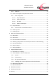
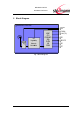
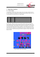
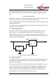
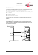
Table Of Contents
- Introduction
- Block Diagram
- Application Interface
- Pin Description
- Electrical Characteristics
- Mechanical Characteristics
- Approvals/Certifications
- Related Documents
- Ordering Information
- History

BlueMod+C11/G2
Hardware Reference
www.stollmann.de Page 9 of 42
Each supply rail should be fed with 3,3V, Range 3,0V to 3,6V incl. Noise, low noise
from a linear regulator with fast transient response. Stollmann suggest using two
pcs.
TOREX: XC6204B332MR
regulators, so that the fast current transients of the class1 RF power amplifier do not
interfere with sensitive PLL circuitry of the low power RF circuitry.
For layout guidelines please see sample implementation Stollmann reference design
BlueMod+Eval/C11/G2.
Excessive noise or too slow current transient response on the supply rails may have
an impact on the RF performance.
3.2 Power-up slew-rate
The Power up slew-rate for the BlueMod+C11/G2 must be more then 6V/ms for
proper startup of the AT91SAM7S Controller used on the BlueMod+C11/G2.
Figure 3 shows an example circuit for a power supply. The Output Voltage of the
Regulator is enabled by the Threshold Voltage of a RESET-Circuit, when VCC Star-
tup ramp reaches a valid Voltage.
Vin
RESET
Enable
Vout
TOREX: XC6204B332MR
VCC 3V3
Vth ~ 2.8 - 3.3V
Figure 3 power supply example circuit
3.3 Power-On-Reset
The BlueMod+C11/G2 is equipped with circuitry for generating Power-On Reset and
to provide under-voltage supervision. An integrated circuit type Maxim DS1818R
provides this functionality.
A reset is generated if the 3.3V supply rail including noise falls below 2,8V to 2,97V.
Via Pin A-1 an external reset can be generated by holding EXT-RES# at ≤ 0.3V for
≥ 10ms. A 74LVC14 Schmitt Trigger gate with a 1kR5/10nF low-pass filter at the
input is implemented to avoid false reset pulse recognition due to EMC effects.
If EXT-RES# is not used, it may be left open or tied to VCC.