
User's Manual
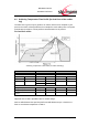
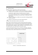
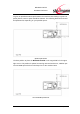
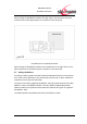
Table Of Contents
- Introduction
- Block Diagram
- Application Interface
- Pin Description
- Electrical Characteristics
- Mechanical Characteristics
- Approvals/Certifications
- Related Documents
- Ordering Information
- History

BlueMod+C11/G2
Hardware Reference
www.stollmann.de Page 34 of 42
To give an optimized antenna performance the restricted area having no ground or
power planes, traces or parts should be widened. The following dimensions should
be implemented, depending on your possible space.
Optimal placement
The best position to place the BlueMod+C11/G2 on the target PCB is in the upper
right corner. This position is optimal concerning antenna interference; radiation pat-
tern and PCB space that has to be keep free for the restricted area.
recomendable placement