
User's Manual
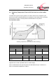
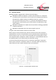
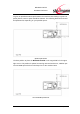
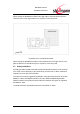
Table Of Contents
- Introduction
- Block Diagram
- Application Interface
- Pin Description
- Electrical Characteristics
- Mechanical Characteristics
- Approvals/Certifications
- Related Documents
- Ordering Information
- History

BlueMod+C11/G2
Hardware Reference
www.stollmann.de Page 33 of 42
6.6 Antenna Issues
BlueMod+C11/G2 is shipped with 3 different antenna designs:
BlueMod+C11/G2/-AI comprises a ceramic antenna which as a component
is soldered to the circuit board. This is functional for a BlueMod+C11/G2/-AI
integrated into a plastic housing. No additional antenna is required.
For an external antenna to be set in, e.g. because the BlueMod+C11/G2 is
integrated into a metal housing, the ceramic antenna is replaced by 2 alter-
native solutions
BlueMod+C11/G2/AE has a UMP connector (50 Ohm technology) populated
as Antenna Interface
BlueMod+C11/G21/AP routes the antenna signal to pin A27.
The gain of the external antenna shall not exceed +2dB
i
.
When using an external Antenna the antenna is fixed and cannot be removed or
replaced by the end user. The performance of the internal antenna respectively the
external antenna has in any case to be checked within the final integration environ-
ment. Adjacent PCBs, components, cables, housings etc. could otherwise influence
the radiation pattern or be influenced by the radio wave energy.
It must be ensured that the antenna is not co-located or operating in conjunction
with any other antennas, transmitters, cables or connectors. When the internal ce-
ramic antenna is used, certain restrictions are to be considered.
Antenna – recommended restricted area