
User's Manual
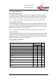
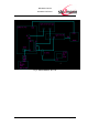
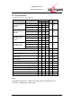
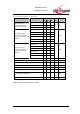
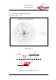
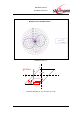
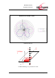
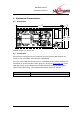
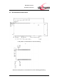
Table Of Contents
- Introduction
- Block Diagram
- Application Interface
- Pin Description
- Electrical Characteristics
- Mechanical Characteristics
- Approvals/Certifications
- Related Documents
- Ordering Information
- History

BlueMod+C11/G2
Hardware Reference
www.stollmann.de Page 29 of 42
6 Mechanical Characteristics
6.1 Dimensions
in solder stop
PCB Manufacturer ID
UL marking top
0,15
+0,1
-0,1
47,5
+0,1
-0,1
0,15
+0,1
-0,1
20,4
+0,0
-0,2
20,0
+0,1
-0,1
Module Height: 3,3 –0/+0,1 mm
6.2 Connectors
Except for the stamp pins A-[1-17,26-28] and C-[1-16] and the UMP antenna con-
nector no user accessible connectors are implemented.
If the use of the UMP antenna connector is considered, please contact Stollmann for
information on accessories like cables, plugs etc. Or look at www.radiall.com for the
UMP type family. On the BlueMod+C11/G2 the following receptacle will be popu-
lated for RF signal routing, if the BlueMod+C11/G2/AE variant is ordered.
Manufacturer
Type
Radiall
RADIALL: R107103020 UMP connector receptacle